A.3.3 motion monitor parameters – Yaskawa MP920 User's Manual Design User Manual
Page 547
Appendix A
A.3.3 Motion Monitor Parameters
A-32
A.3.3
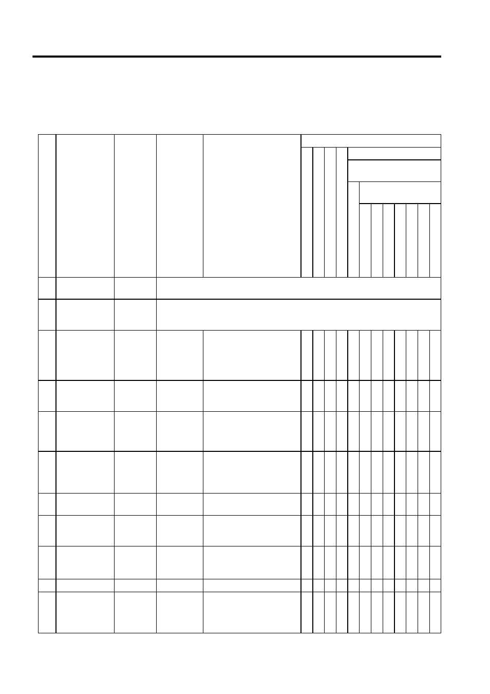
Motion Monitor Parameters
The following table lists motion monitor servo parameters.
No.
Name
Register
Number
Setting
Range
Meaning
Control Mode Where Data Is Valid
Zero Point Return Mode
S
pee
d Control Mode
To
rq
ue Control
Mod
e
Pha
se C
ontrol
Mode
Position Control Mode
Motion Command
Code (OB008)
Motion
Co
mma
nd
Disab
led
Motion Command
Code (OW20)
Positioning
External
Posi
tion
Zero Poin
t Return
Interpol
ation
La
tch
F
eed
St
ep
1
RUN Status
(RUNSTS)
IW00
Reports the SVA Module operation status.
2
General-purpose
DI Monitors
(SVSTS)
IW01
Reports the status of general-purposeDI signals, or input signals from SERVOPACK.
3
Calculated Posi-
tion in Machine
Coordinate
System
(CPOS)
IL02
-2
31
to 2
31
-1
1 = 1 pulse or 1 = 1 reference
unit
1 = 1 pulse for pulses
Updated when the machine is
locked.
√
√ √ √ √ √ √ √ √ √
5
Target Position
Difference Mon-
itor (PTGDIF)
IL04
-2
31
to 2
31
-1
1 = 1 pulse or 1 = 1 reference
unit
1 = 1 pulse for pulses
√
√ √ √ √ √ √ √ √ √
7
Machine Coordi-
nate System
Latch Position
(LPOS)
IL06
-2
31
to 2
31
-1
1 = 1 reference unit
(1 = 1 pulse for pulses)
√ √ √ √ √ √ √
√ √ √ √
9
Machine Coordi-
nate System
Feedback Posi-
tion (APOS)
IL08
-2
31
to 2
31
-1
1 = 1 reference units
(1 = 1 pulse for pulses)
Note: Will not be updated if
the machine is locked.
√ √ √ √ √ √ √ √ √ √ √ √
11
Position Error
(PERR)
IL0A
-2
31
to 2
31
-1
1 = 1 reference unit
(1 = 1 pulse for pulses)
√
√ √ √ √ √ √ √ √ √
13
Speed Reference
Output Monitor
(SPDREF)
IW0C
-32768 to
32767
1 = 0.01%
√ √ √ √ √ √ √ √ √ √ √ √
14
Speed Monitor
(NFB)
IW0D
-32768 to
32767
1 = 0.01%
Note: Valid only with a 2-axis
SVA Module.
√ √ √ √ √ √ √ √ √ √ √ √
15
Not used
IW0E
−
−
16
Out of Range
Parameter Num-
ber (ERNO)
IW0F
1 to 63
101 to 148
Set motion parameter error
number
Fixed motion parameter error
number
√ √ √ √ √ √ √ √ √ √ √ √