Pulse input connectors pulse input connector 1 – Yaskawa MP920 User's Manual Design User Manual
Page 239
5 Modules
5.3.4 CNTR-01 Counter Module
5-44
The table below shows the LED indicator patterns when an error occurs in the CNTR-01
Module.
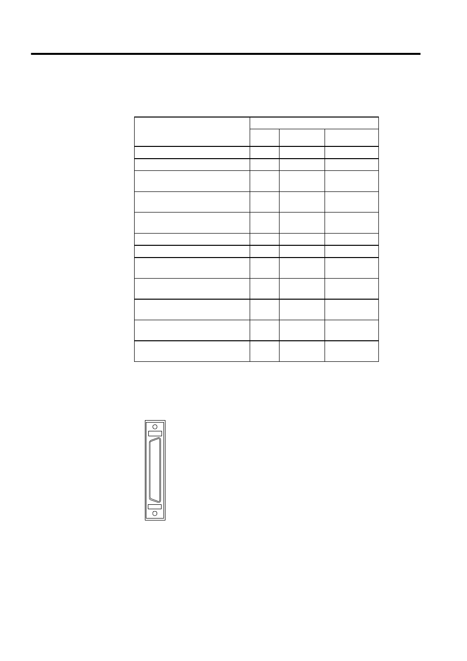
Pulse Input Connectors
Pulse Input Connector 1
Error Contents
(Detected by Online Self-diagnosis
Function)
LED Indicator
RUN
ERR
CH1 to CH4
ROM diagnostic error
Lit
Blinks once
Not specified
RAM diagnostic error
Lit
Blinks twice
Not specified
Shared memory diagnostic error
Lit
Blinks three
times
Not specified
CPU built-in timer diagnostic error
Lit
Blinks four
times
Not specified
Timer diagnostic error
Lit
Blinks five
times
Not specified
Illegal general instruction interrupt
Unlit
Blinks once
Not specified
Illegal slot instruction interrupt
Unlit
Blinks twice
Not specified
CPU address error interrupt
Unlit
Blinks three
times
Not specified
DMA address error interrupt
Unlit
Blinks four
times
Not specified
User break interrupt
Unlit
Blinks five
times
Not specified
Trap instruction interrupt
Unlit
Blinks six
times
Not specified
Watchdog timeout error
Lit
Blinks fif-
teen times
Not specified
5-V Differential type pulse input connector
The CN1 connector is used to connect 5-V differential type pulse
input signals to the CNTR-01 Module
Number of channels: 4
CN1