Zero point return method – Yaskawa MP920 User's Manual Design User Manual
Page 170
4 Motion Control
4.4.4 Zero Point Return (ZRET)
4-56
Zero Point Return Method
The following methods are available with the zero point return (ZRET) motion command.
• With a limit switch (deceleration limit switch) and a zero point return limit signal, a user program
must be created to connect the LIO-01 or other external DI signal to the next motion setting param-
eters.
• Limit Switch Signal*:
OB01F
• Reverse Limit Signal for Zero Point Return: OB21C
• Forward Limit Signal for Zero Point Return:OB21D
* DI5 (DI signal) can also be used with a 4-axis SVA-01A Module. Whether
a DI signal or OB01F is used as the limit switch signal is set in the bit
2 in motion fixed parameter No. 14 (Additional Function Selections).
• A limit switch (deceleration limit switch) signal’s polarity can be reversed using the setting of bit
10 (Deceleration Limit Switch Inversion Selection) in motion fixed parameter No. 17 (Motion
Controller Function Selection Flags (SVFUNCSEL)). The default is 0 (do not reverse).
• Refer to 4.2.5 Zero Return Mode for details.
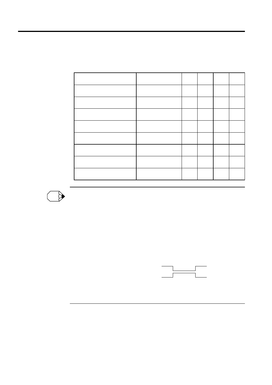
• For the zero point return method, set the fixed parameter No. 31 (Zero Point Return Method) to a
number between 0 and 7.
Zero Point Return Method
Fixed Parameter 31
Setting
SVA-
01A
SVA-
02A
SVB-
01
PO-01
DEC1 + C-phase pulse
0
Appli-
cable
Appli-
cable
Appli-
cable
N/A
DEC2 + C-phase pulse
6
Appli-
cable
Appli-
cable
N/A
N/A
DEC1 + LMT + C-phase pulse
7
Appli-
cable
Appli-
cable
N/A
N/A
C-phase pulse
3
Appli-
cable
Appli-
cable
Appli-
cable
N/A
DEC1 + ZERO signal
2
Appli-
cable
N/A
Appli-
cable
Appli-
cable
DEC2 + ZERO signal
4
Appli-
cable
N/A
N/A
Appli-
cable
DEC1 + LMT + ZERO signal
5
Appli-
cable
N/A
N/A
Appli-
cable
ZERO signal
1
Appli-
cable
N/A
Appli-
cable
N/A
INFO
0: Do not reverse
1: Reverse
Deceleration limit switch
Deceleration limit switch
NC contact
NO contact