Yaskawa MP920 User's Manual Design User Manual
Page 409
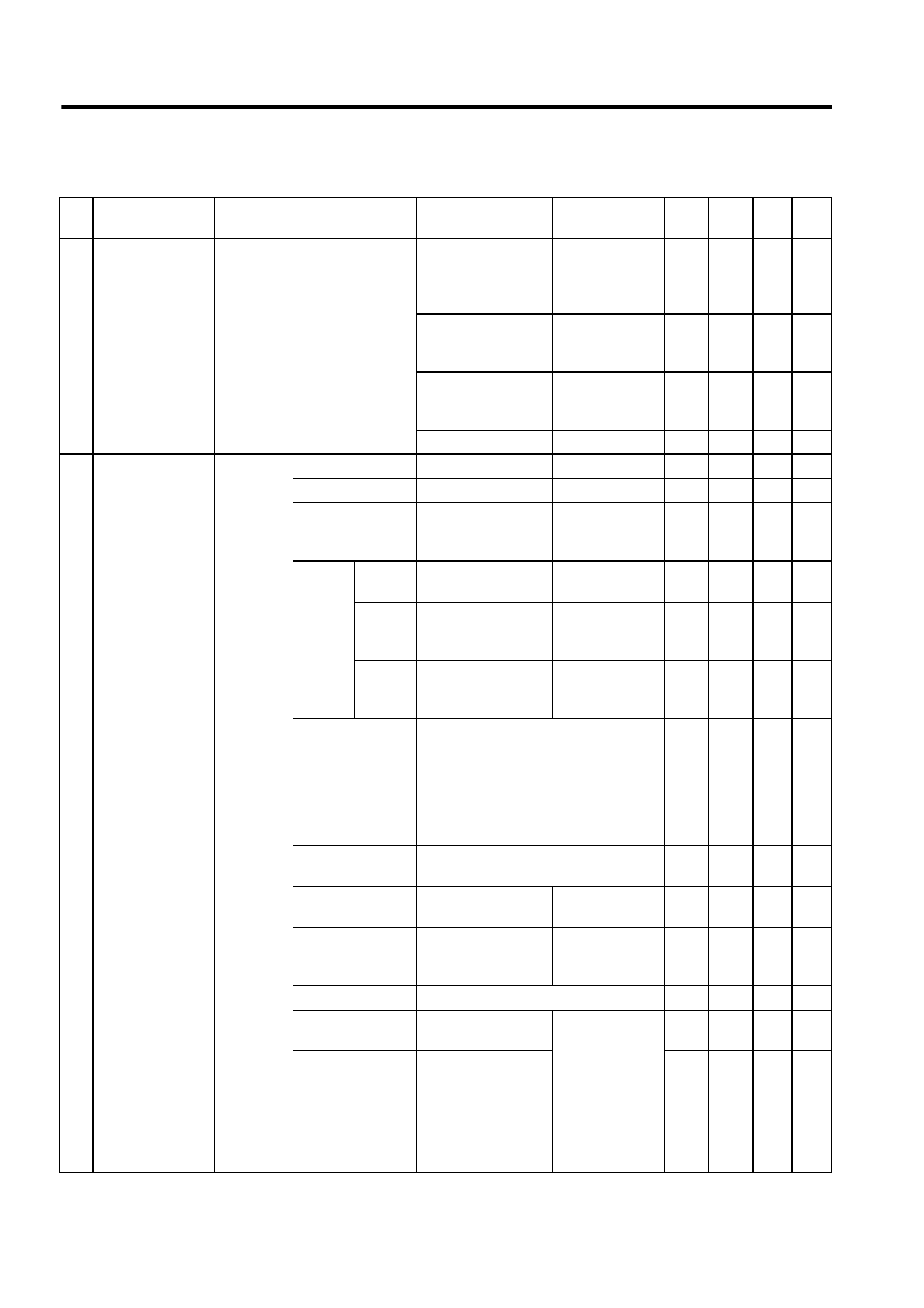
7 Parameters
7.2.2 Motion Setting Parameters
7-14
33 Motion Com-
mand Code
(MCMDCODE)
(cont’d)
OW 20
0 to 65535
(Default = 0)
19: ALM_MON
Monitor current
alarm occur-
rence in servo
driver
9
20: ALMHIST_MON Monitor servo
driver alarm his-
tory
9
21: ALMHIST_CLR
Clear servo
driver alarm his-
tory
9
22 to 65535: Not used
34 Motion Com-
mand Control
Flags
(MCMDCTRL)
(Default = 0, all
the bits are set to
OFF)
OW 21
Bit0: HOLD
Command hold
0: OFF, 1: ON
9
9
9
9
Bit 1: ABORT
Command abort
0: OFF, 1: ON
9
9
9
9
Bit 2: DIRECTION Direction of move-
ment
(For JOG and STEP)
0: Forward
1: Reverse
9
9
9
9
Bit 3:
P_PI
Speed loop P/PI
switching
0: PI
1: P
9
REM-
CUT
No feed speed
remaining compensa-
tion
0: OFF
1: ON
9
LAGRST
No primary lag (Same
as primary lag time
constant = 0)
0: OFF
1: ON
9
9
Bits 4 to 7:
FILTERTYPE
Filter type selection
0: No filter
1: Exponential filter (exponential
acceleration/deceleration)
2: Movement averaging filter
(simple S-curved acceleration/
deceleration)
9
9
9
9
Bit 8: POS_PPI
Position loop P/PI switch
0: P, 1: PI
9
9
Bit 9: POS_IRST
Position control inte-
gration reset
0: OFF
1: ON
9
9
Bit 10: NCOMSEL Speed compensation
(OW
18) during
position control
0: OFF
1: ON
9
9
Bit 11: Not used
−
Bit 12: LMT_L
Reverse limit signal
for zero point return
Valid only when
the fixed parame-
ter No. 14 (Addi-
tional Function
Selection) is set
to OB
21
(setting parame-
ter) used.
0: OFF, 1: ON
9
9
9
Bit 13: LMT_R
Forward limit signal
for zero point return
9
9
9
Table 7.3 Motion Setting Parameters (cont’d)
No.
Name
Register
No.
Setting Range
Meaning
Remarks
SVA-
01A
SVA-
02A
SVB
-01
PO-
01