User program example: zero point return, Important – Yaskawa MP920 User's Manual Design User Manual
Page 182
4 Motion Control
4.4.4 Zero Point Return (ZRET)
4-68
• If the machine is in Area B after the power is turned ON, the return cannot be performed correctly.
Be sure to move the machine back to Area A before performing a return.
• The deceleration limit switch width must be at least twice that of the high-speed scan setting value.
The criteria for the deceleration limit switch width (L) can be calculated using the formula shown
below.
• When a short distance is set for the zero point return final travel distance, the axis returns to the
zero point after the zero point has been passed once.
User Program Example: Zero Point Return
1. Example of RUN Operation
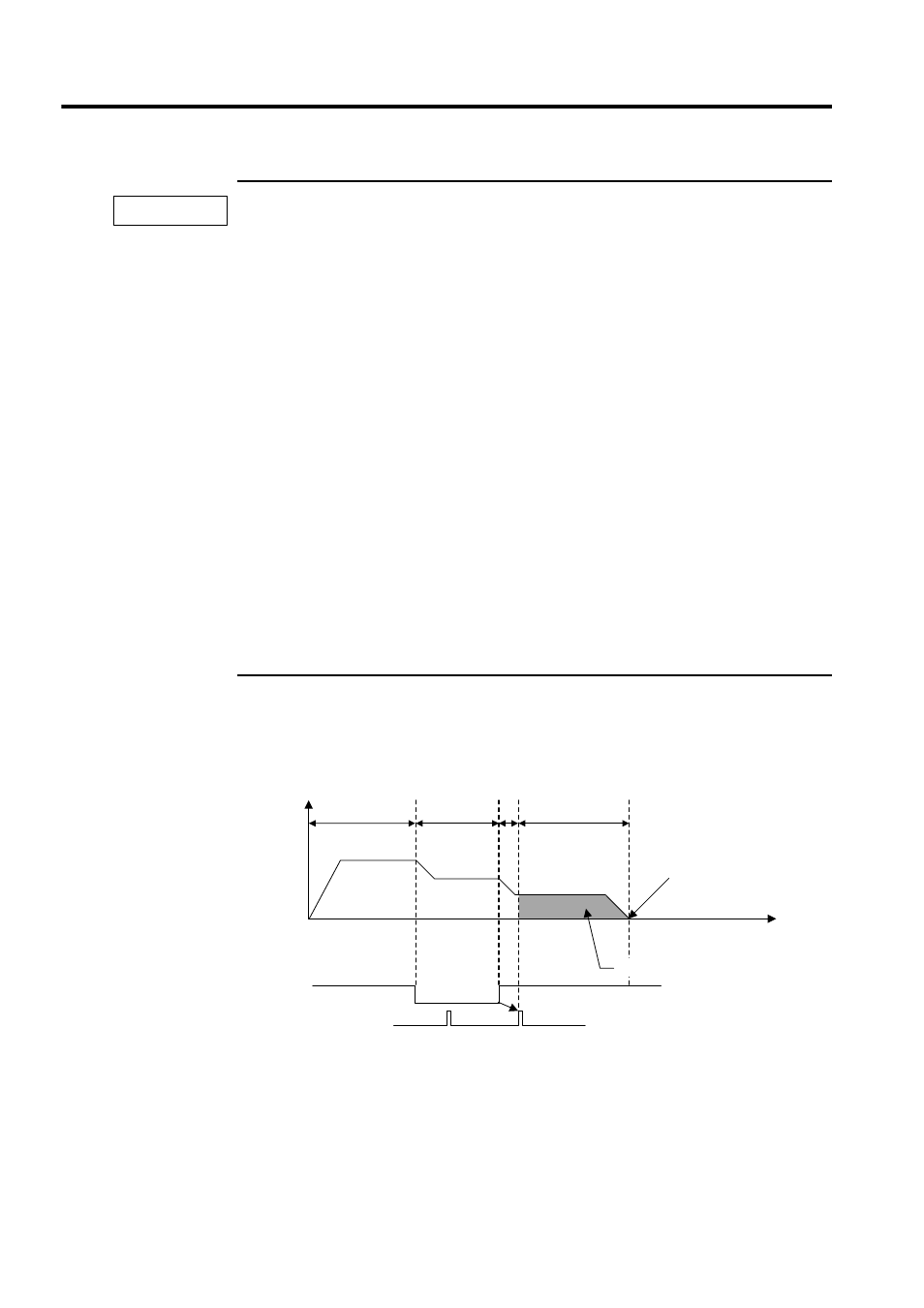
Fig. 4.19 Example of a Zero Point Pattern (DEC1 + C-phase Pulse Signal Method)
•
Ts (s) = High-speed scan set value (ms)/1000
• f (m/s) = K
× {NR × n × FBppr}/60
F
: 100% speed (m/s)
K
: Weight of 1 pulse (m/pulse)
NR
: Rated rotation speed (r/min)
FBppr : Feedback pulse resolution (p/r)
n
: Pulse multiplication (1, 2, or 4)
• t (s) = Linear acceleration/deceleration time (s)
•
α (m/s
2
) = f/t
If
α = acceleration/deceleration time constant (m/s
2
), the
following equation applies.
L = 1/2 ·
α (2 × Ts)
2
= 2
α Ts
2
IMPORTANT
0
1.
2.
3.
4.
Reverse direction
← → Forward direction Zero point
Speed
reference
Rapid traverse
speed
Approach
speed
Creep speed
Zero point return position
Dog
(Deceleration limit switch)
Zero point signal
(C-phase pulse)
Zero point return final travel distance
Time