Connecting the switch box, Switch box external signal allocation – Yaskawa MP920 User's Manual Design User Manual
Page 340
6 System Startup
6.2.2 Connecting Devices
6-10
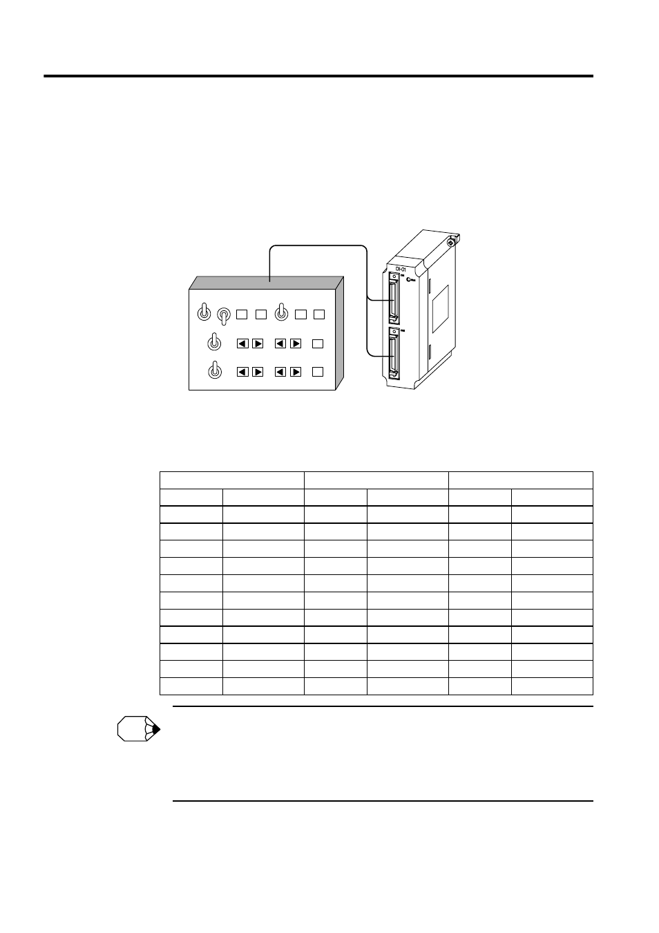
Connecting the Switch Box
The switch box used by the ladder logic program that is automatically generated on the
Group Definition Window is connected as shown in the following illustration.
• Axis input signals: DI-01 Module CN1 connector
Switch Box External Signal Allocation
Allocate the switch box signals as shown in the following table.
By default, the group input signals and axis input signals are allocated sequentially starting from
IB00000. When a test must be conducted without connecting the input signal lines, it is convenient to
set the M registers.
Turning ON or OFF the signals on the Register List Window has the same effect as using the switch
box.
OFF
JOG
ZRN
STEP
OFF
JOG
ZRN
STEP
Input Module
Automatic Manual
Start
Reset
Pause
Emergency
stop
Alarm
reset
Servo ON
Servo ON
Axis 1:
Axis 2:
Group Input Signals
Axis 1 Input Signals
Axis 2 Input Signals
IB00000
Automatic mode
IB00010
Servo ON
IB00020
Servo ON
IB00001
Manual mode
IB00011
JOG+
IB00021
JOG+
IB00002
Start
IB00012
JOG-
IB00022
JOG-
IB00003
Reset
IB00013
STEP+
IB00023
STEP+
IB00004
Pause
IB00014
STEP-
IB00024
STEP-
IB00005
Emergency stop
IB00015
ZRN
IB00025
ZRN
IB00006
Alarm reset
−
−
−
−
IB00007
−
−
−
−
−
IB00008
−
−
−
−
−
IB00009
−
−
−
−
−
IB0000A
−
−
−
−
−
IB0000B
−
−
−
−
−
INFO