External signal allocation, Registers in the main ladder logic program (h01) – Yaskawa MP920 User's Manual Design User Manual
Page 371
6.2 System Startup Procedure
6-41
6
External Signal Allocation
The external signals used by motion management ladder logic programs are allocated
according to the group definition as shown in the following table.
Registers Used by Motion Management Ladder Logic Programs
Data Transfer between Main and Subroutine Logic Programs
MW00002 (1 word) is used as the register for data transfer between main and subroutine
logic programs.
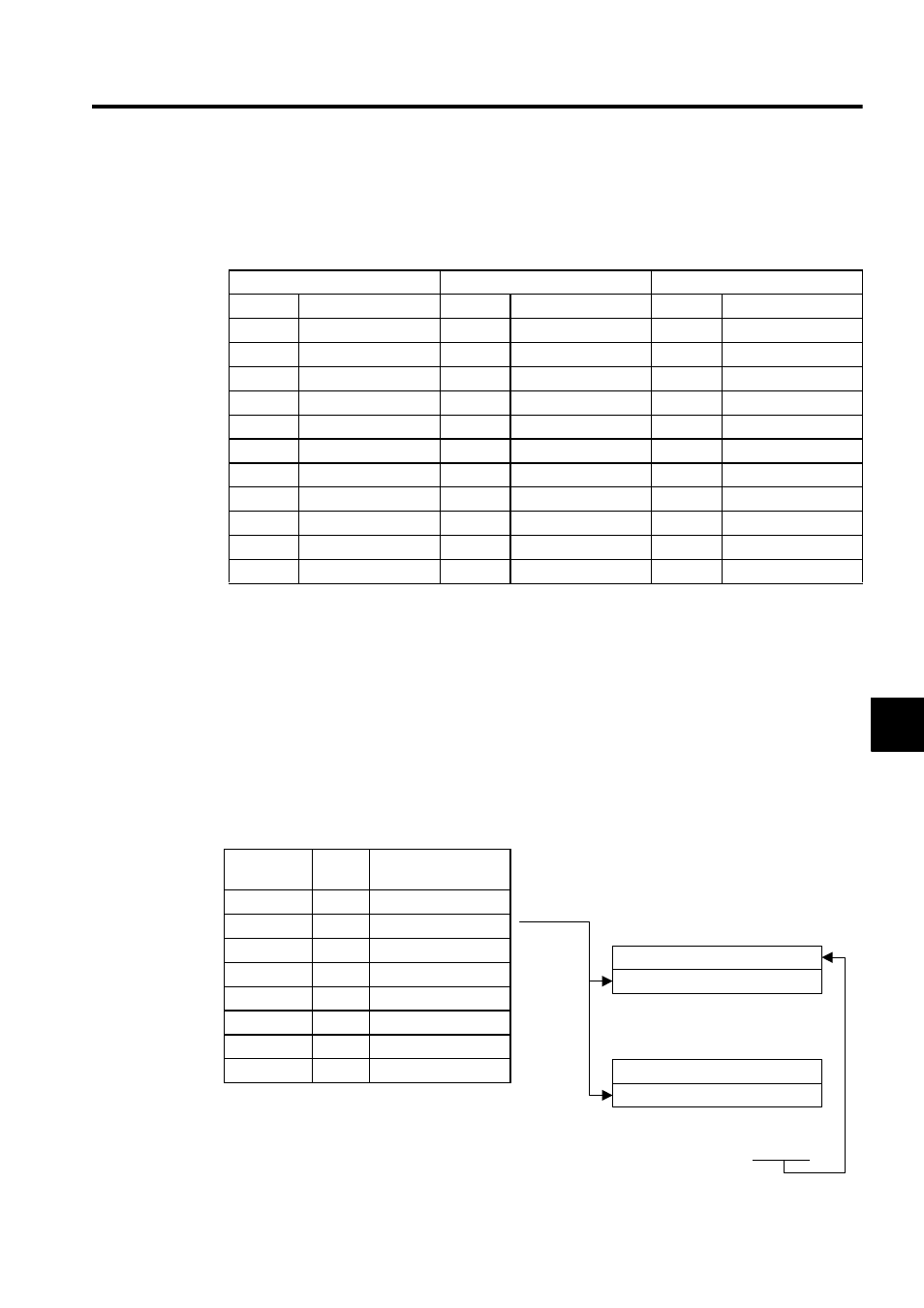
Registers in the Main Ladder Logic Program (H01)
The following illustration shows the configuration of the group work registers used by the
main ladder logic program.
Fig. 6.2 Group Work Register Configuration
Group Input Signals
Axis 1 Input Signals
Axis 2 Input Signals
IB00000
Automatic mode
IB00010
Servo ON
IB00020
Servo ON
IB00001
Manual mode
IB00011
JOG+
IB00021
JOG+
IB00002
Start
IB00012
JOG-
IB00022
JOG-
IB00003
Reset
IB00013
STEP+
IB00023
STEP+
IB00004
Momentary stop
IB00014
STEP-
IB00024
STEP-
IB00005
Emergency stop
IB00015
ZRN
IB00025
ZRN
IB00006
Alarm reset
IB00016
Zero point setting
IB00026
Zero point setting
IB00007
Machine lock setting
IB00017
Stop
IB00027
Stop
IB00008
Block operation mode
−
−
−
−
IB00009
Block operation
−
−
−
−
IB0000A
Skip 1 operation
−
−
−
−
IB0000B
Skip 2 operation
−
−
−
−
Register
Number
Size
Description
DW00100
1 word
Group status
DW00101
1 word
Group control signal
DW00102
1 word
Automatic, common
DW00103
1 word
Manual, common
DW00104
1 word
Axis 1 manual status
DW00105
1 word
Axis 2 manual status
:
:
DW00151
1 word
Axis 48 manual status
MSEE MPM001DA00000
Copied
Task 1 program status
Task 1 program control signal
Task n program status
Task n program control signal