Remote output module connector wiring, Info, 2 system startup procedure 6-9 – Yaskawa MP920 User's Manual Design User Manual
Page 339
6.2 System Startup Procedure
6-9
6
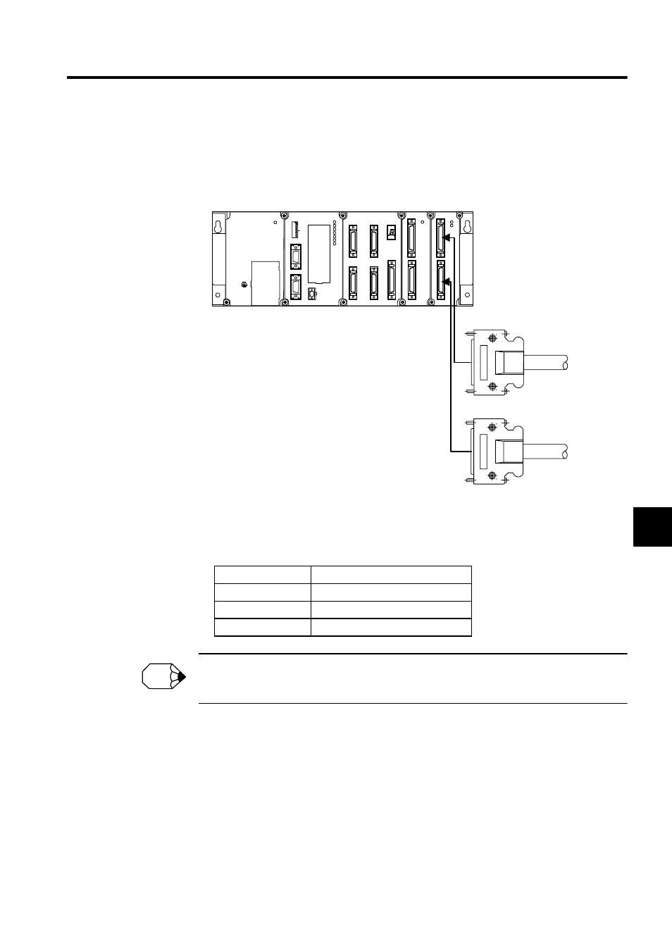
Remote Output Module Connector Wiring
The following illustration shows the method of connecting the external output signal termi-
nals and the DO-01 Output Module connectors.
When connecting the external output signal terminals and the DO-01 Output Module con-
nector, use the following cables.
See 5.3.2 DO-01 Output Module for the DO-01 Output Module connector specifications, connector
pin layout, and connection examples.
External Output Cables
Cable Length
Model
0.5 m
JEPMC-W6060-05
1 m
JEPMC-W6060-10
3 m
JEPMC-W6060-30
SW1
L.RST
RUN
INIT
TEST
MULTI
FLASH
M.RST
ON
OFF
ON
1
2
3
4
5
6
7
8
PORT2
PORT1
CN1
RLY OUT
BATTERY
RDY
PRT1
RUN
ALM
ERR
BAT
ALM
PRT2
MP920 CPU-01
SVA-01
CN1
CN3
CN2
CN4
STATUS
CN5
DI-01
CN1
CN2
RUN
DO-01
CN1
CN2
RUN
FUSE
PS-03
DC24V
POWER
TB1
+24V
0V
FG
SG
To external
output signal
terminals
To external
output signal
terminals
PS-03
CPU-01
SVA-01A
DI-01 DO-01
To CN1 connector
To CN2 connector
INFO
- Tag Generator (30 pages)
- MP3300iec (82 pages)
- 1000 Hz High Frequency (18 pages)
- 1000 Series (7 pages)
- PS-A10LB (39 pages)
- iQpump Micro User Manual (300 pages)
- 1000 Series Drive Option - Digital Input (30 pages)
- 1000 Series Drive Option - CANopen (39 pages)
- 1000 Series Drive Option - Analog Monitor (27 pages)
- 1000 Series Drive Option - CANopen Technical Manual (37 pages)
- 1000 Series Drive Option - CC-Link (38 pages)
- 1000 Series Drive Option - CC-Link Technical Manual (36 pages)
- 1000 Series Drive Option - DeviceNet (37 pages)
- 1000 Series Drive Option - DeviceNet Technical Manual (81 pages)
- 1000 Series Drive Option - MECHATROLINK-II (32 pages)
- 1000 Series Drive Option - Digital Output (31 pages)
- 1000 Series Drive Option - MECHATROLINK-II Technical Manual (41 pages)
- 1000 Series Drive Option - Profibus-DP (35 pages)
- AC Drive 1000-Series Option PG-RT3 Motor (36 pages)
- Z1000U HVAC MATRIX Drive Quick Start (378 pages)
- 1000 Series Operator Mounting Kit NEMA Type 4X (20 pages)
- 1000 Series Drive Option - Profibus-DP Technical Manual (44 pages)
- CopyUnitManager (38 pages)
- 1000 Series Option - JVOP-182 Remote LED (58 pages)
- 1000 Series Option - PG-X3 Line Driver (31 pages)
- SI-EN3 Technical Manual (68 pages)
- JVOP-181 (22 pages)
- JVOP-181 USB Copy Unit (2 pages)
- SI-EN3 (54 pages)
- MECHATROLINK-III (35 pages)
- SI-ET3 (49 pages)
- EtherNet/IP (50 pages)
- SI-EM3 (51 pages)
- 1000-Series Option PG-E3 Motor Encoder Feedback (33 pages)
- 1000-Series Option SI-EP3 PROFINET (56 pages)
- PROFINET (62 pages)
- AC Drive 1000-Series Option PG-RT3 Motor (45 pages)
- SI-EP3 PROFINET Technical Manual (53 pages)
- A1000 Drive Option - BACnet MS/TP (48 pages)
- 120 Series I/O Modules (308 pages)
- A1000 12-Pulse (92 pages)
- A1000 Drive Software Technical Manual (16 pages)
- A1000 Quick Start (2 pages)
- JUNMA Series AC SERVOMOTOR (1 page)
- A1000 Option DI-101 120 Vac Digital Input Option (24 pages)