3 external positioning (ex_posing), Ladder logic program example, Overview – Yaskawa MP920 User's Manual Design User Manual
Page 165
4.4 Position Control Using Motion Commands
4-51
4
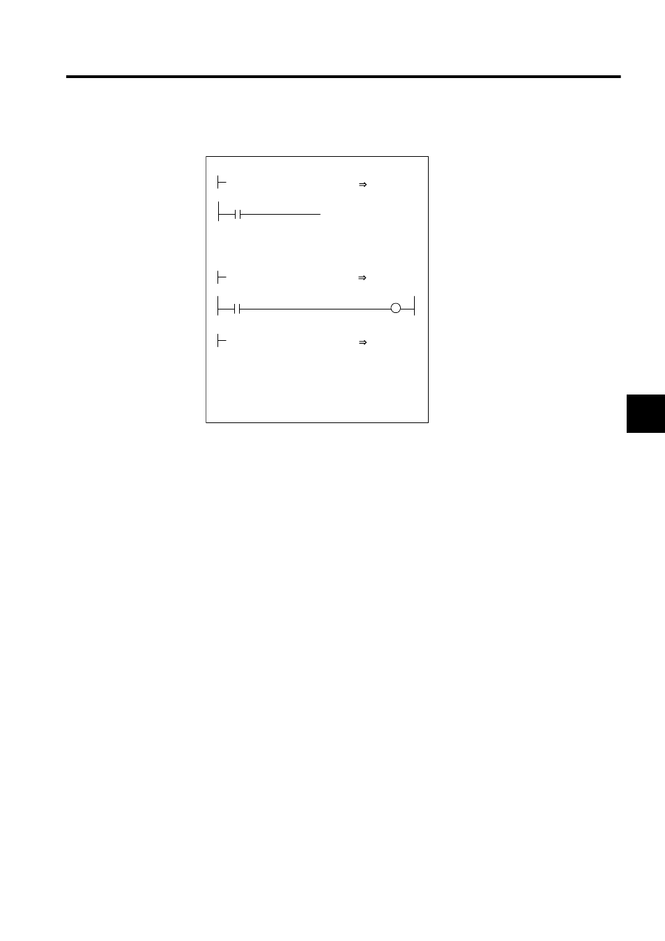
Ladder Logic Program Example
Fig. 4.16 Positioning Programming Example (DWG H03)
The example in the above illustration has been greatly simplified. In actual operation, each
register can be controlled from the user program.
4.4.3
External Positioning (EX_POSING)
Overview
In the same way as the positioning (POSING) command, the external positioning
(EX_POSING) command positions the axis at the position reference position using the spec-
ified acceleration/deceleration time constant and the specified rapid traverse speed.
If a latch signal (external positioning signal) is input while at the feed speed, external posi-
tioning uses the latch signal to latch the current position, and positions the axis at a position
where it has traveled the external positioning travel distance set as a parameter from that
position.
When the specified external positioning travel distance is less than the deceleration distance,
the system first decelerates to a stop and then is repositioned according to the position refer-
ence value.
The external positioning travel distance can be changed before the latch signal (external posi-
tioning signal) is input.
A specific discrete input (DI input) is used for the latch signal (external positioning signal).
IFON
H0104
RUNMOD
OWC000
0000010000
XREF
OLC012
RUN
OBC0010
SB000004
1
MCMDCODE
OWC020
IEND
DEND
RUNPB
IB00304
Set the position control mode to ON.
Execute positioning (POSING) as the motion
command.
Driver operation command (RUN)
Position reference pulse (XREF)
(Absolute position: 10000)
When IB00304 turns ON, position control
starts, and the axis moves to absolute position
10000. When absolute position 10000 is
reached, the IBC000D positioning completed
signal turns ON.