9 zero point setting (zset), Warning, Ladder logic program example – Yaskawa MP920 User's Manual Design User Manual
Page 194
4 Motion Control
4.4.9 Zero Point Setting (ZSET)
4-80
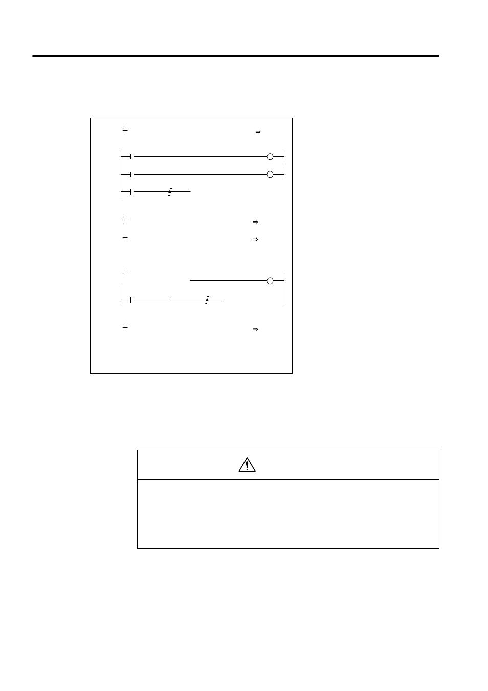
Ladder Logic Program Example
The example in the above illustration has been greatly simplified. In actual operation, each
register can be controlled from the user program.
4.4.9
Zero Point Setting (ZSET)
Set the position control mode to ON.
RUN command to the driver.
When IB00303 turns ON, the rotation direction
will be changed to the reverse direction.
STEP travel amount: 2,000 pulses
When IB00304 turns ON, the STEP operation
starts and the axis will move for the STEP
travel amount.
When the axis moved for the STEP travel
amount, the positioning completed signal
(IBC00D) will turn ON.
After the positioning has been completed,
set NOP to clear the command.
H0104
RUNMOD
OWC000
1 0000
$ONCOIL
SB000004
IB00303
RUN
OBC0010
1 0002
1 0004
IB00304
1 0006
1 0008
IFON
MCMDRCOD
IWC014
1 0014
00008
DIRECTION
OBC0212
DB000010
00008
MCMDCODE
OWC020
2 0011
05000
STEP
OWC028
2 0009
1 0013
IEND
DB000020
POSCOMP
IBC000D
1 0017
DB000030
DB000020
1 0020
IFON
00000
MCMDCODE
OWC020
1 0021
1 0023
IEND
0 0024
DEND
• The zero return setting (ZSET) command is used to set the machine coordinate system
zero point. Therefore, if the ZSET setting position is incorrect, the movement for subse-
quent operations will differ from the actual position. Before executing operations, be
sure to check that the correct machine coordinate system zero point has been set.
Failure to carry out this check may result in damage to equipment, serious personal injury, or
even death.
WARNING