Yaskawa MP920 User's Manual Design User Manual
Page 286
5.5 Motion Modules
5-91
5
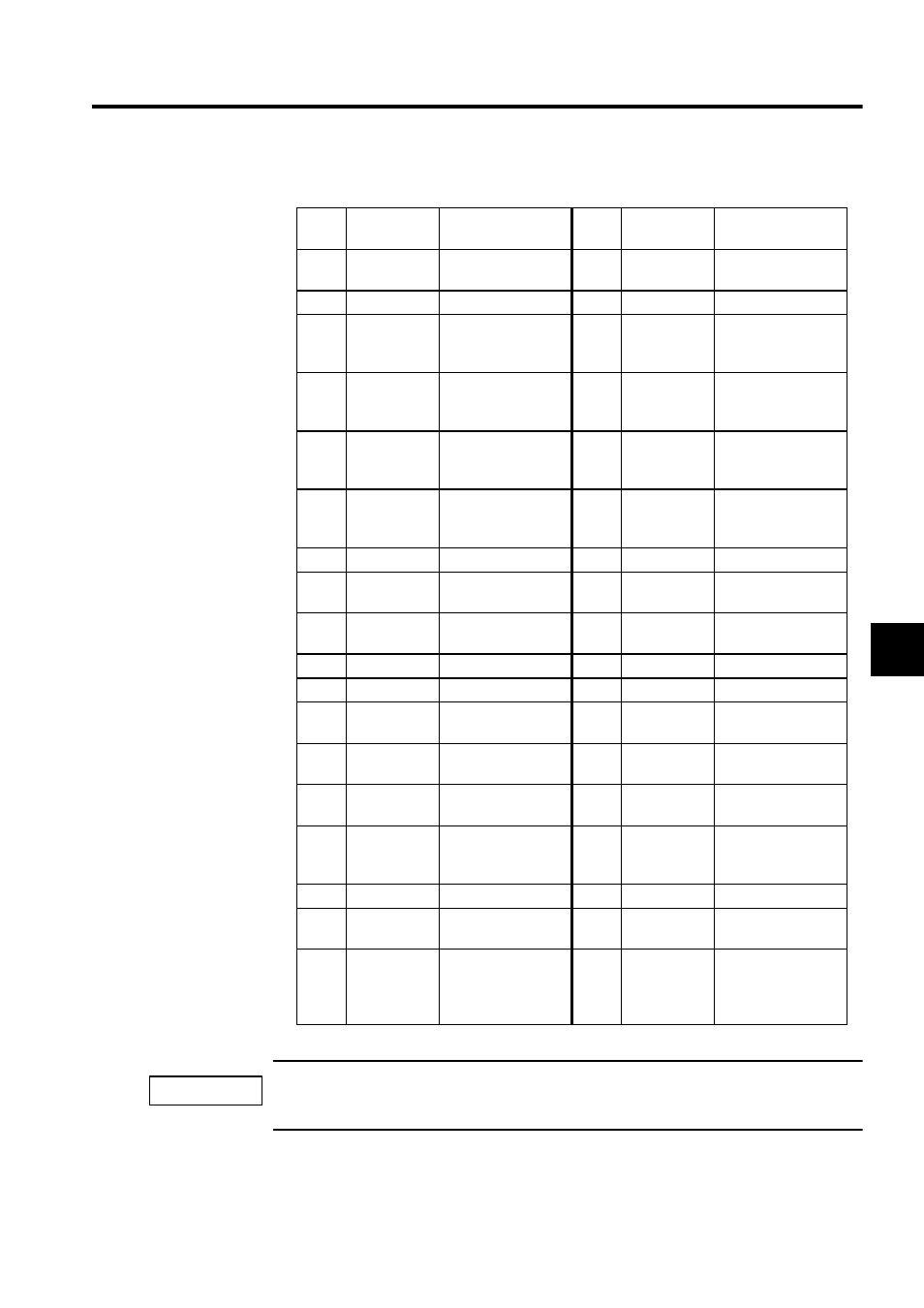
The following table shows the names and functions of the CN1/CN2 connector pins.
Either 5 V or 24V can be selected for the SEN signal. Connect the SEN signal to either Pin 20 or Pin
32 according to the application. The standard cable is to connected to the Pin 20 (5 V).
Pin
No.
Signal Name
Function
Pin
No.
Signal Name
Function
1
SG
Ground
(for analog)
19
SG
Ground
(For SEN signal)
2
NREF
Speed reference
20
SEN (5V)
SEN signal
3
PA
5-V differential
phase-A pulse input
(+)
21
Unused
4
PAL
5-V differential
phase-A pulse input
(-)
22
Unused
5
PC (5 V)
5-V differential
phase-C pulse input
(+)
23
PB
5-V differential
phase-B pulse input
(+)
6
PCL (5 V)
5-V differential
phase-C pulse input
(-)
24
PBL
5-V differential
phase-B pulse input
(-)
7
SG
Ground
25
SG
Ground
8
AI-IN
Analog input
26
AI-GND
Analog input
ground
9
AO-OUT
Analog output
27
AO-GND
Analog output
ground
10
0V (24V)
0 V (24 V)
28
0V (24V)
0 V (24 V)
11
0V (24V)
0 V (24 V)
29
0V (24V)
0 V (24 V)
12
PCON
P operation refer-
ence, DO-2
30
ALM RST
Alarm reset
DO-1
13
OTR
Overtravel (-)
,
DO-4
31
SV ON
Servo ON
DO-0
14
OTF
Overtravel (+), DO-3
32
SEN (24V)
SEN output for
VS866
15
General-pur-
pose DI
General-purpose
input
(OTF) DI-3
33
General-pur-
pose DI
General-purpose
input (OTR) DI-4
16
+24V
+24 V power supply
34
+24V
+24V power supply
17
SV ALM
Servo alarm input,
DI-0
35
SRDY
Servo ready input
DI-1
18
BRK
Brake ON input, DI-
2
36
General-pur-
pose DI
General-purpose
input DI-5
(External position-
ing latch)
IMPORTANT