2 operation, Connecting the mpe720 programming device, Fig. 9.2 multi-cpu system function block diagram – Yaskawa MP920 User's Manual Design User Manual
Page 430: Cpu module 1 cpu module 2
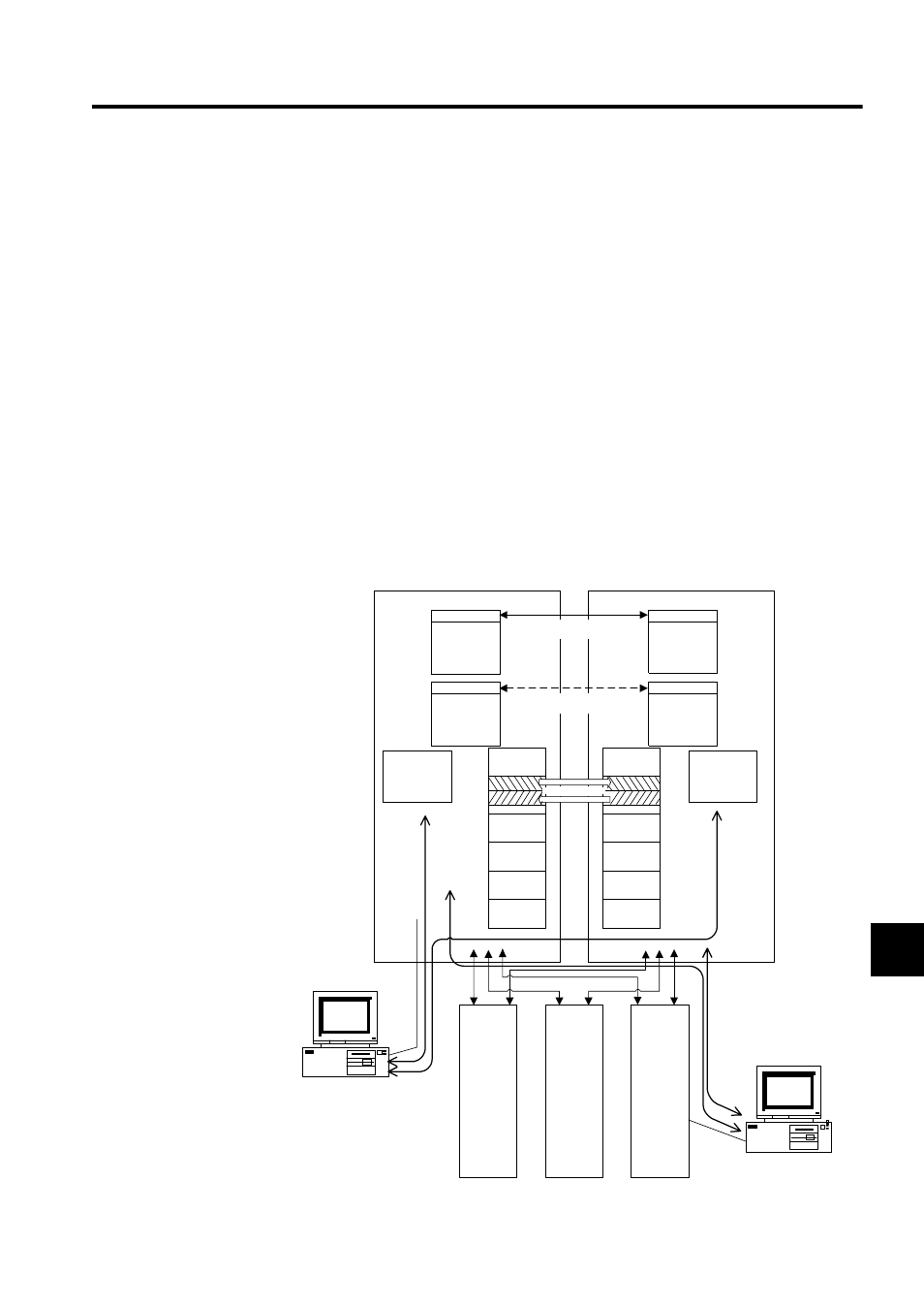
9.1 Overview
9-3
9
9.1.2
Operation
The CPU Module mounted in slots 0 and 1 of the Mounting Base is called CPU Module 1,
and the CPU Module mounted in the slots 2 and 3 of the Mounting Base is called CPU Mod-
ule 2. This section describes the functions and processing assigned to CPU Module 1 and
CPU Module 2 and the operation of the system.
Connecting the MPE720 Programming Device
It is possible to log on to both CPU Module 1 and CPU Module 2 from one MPE720 Pro-
gramming Device without changing the cable connection for engineering operations, such as
setup, programming, and register display. For example, it is possible to log on to both CPU
Module 1 and CPU Module 2 from a Programming Device connected to the RS-232C port
of CPU Module 1 or from a Programming Device connected via a Communications Module,
such as the 217IF, 218IFA, and 215IF. Logging on to both CPU Module 1 and CPU Module
2 is possible via a Communications Module no matter which CPU Module is specified as the
Control CPU Module described in Controlling Optional Modules in this section.
Fig. 9.2 Multi-CPU System Function Block Diagram
MPE720
Programming Device
MPE720
Programming Device
CPU Module 1
CPU Module 2
H scan
H scan
User ladder
/motion
programs
User ladder/
motion
programs
L scan
L scan
User ladder/
motion
programs
User ladder/
motion
programs
Data memory
Others
Data memory
M registers
I registers
O registers
S registers
I registers
O registers
S registers
Others
Configuration
data
(For CPU
Module 1)
(For CPU
Module 1)
(For CPU
Module 1)
(For CPU
Module 2)
(For CPU
Module 2)
(For CPU
Module 2)
Configuration
data
Motion
Modules
I/O Modules
Communications
Modules
(217IF,
218IFA,
215IF)
(DI, DO, AI, AO,
LIO, CNTR, etc.)
(SVA, SVB, PO)
M registers
Shared memory
H (high-speed) scans
can be synchronized.
L (low-speed) scans
can be synchronized.