Yaskawa MP920 User's Manual Design User Manual
Page 68
2 MP920 Specifications and System Configuration
2.2.1 List of Basic Modules
2-42
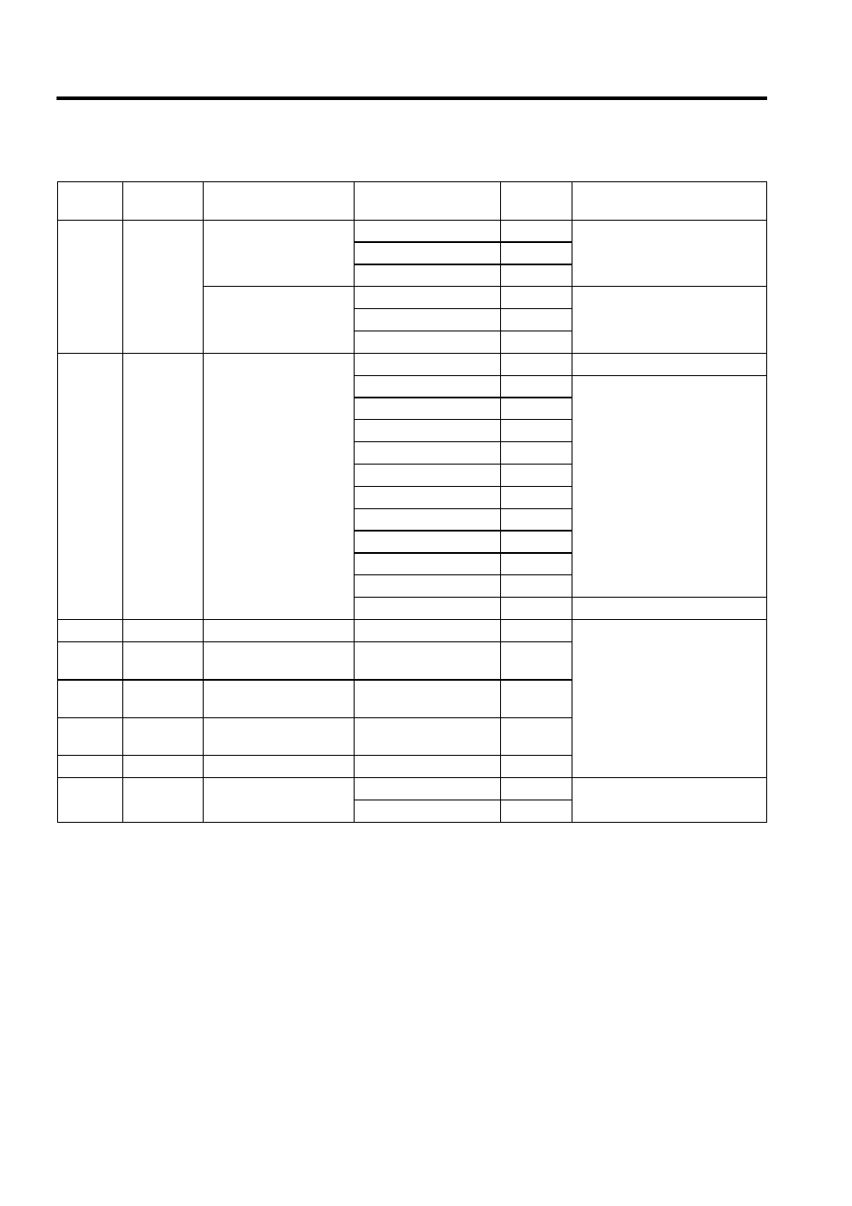
Note: Standard JEPMC-W6060-05, JEPMC-W6060-10, and JEPMC-W6060-30 Cables (with
connector at one end only) are used to connect SVA-01A Modules (CN5), DI-01 Modules,
DO-01 Modules, LIO-01 Modules, CNTR-01 Modules, and PO-01 Modules. There are
many cables that use the same connectors. To avoid connecting cables incorrectly, distin-
guish the cables using color tape or by placing labels on the connectors.
SVA-02A CN1 or CN2 Analog Servo interface
(SGDA)
JEPMC-W6070-05
0.5 m
SVA-02A
⇔ SGDA
JEPMC-W6070-10
1.0 m
JEPMC-W6070-30
3.0 m
Analog Servo interface
(SGDB)
JEPMC-W6071-05
0.5 m
SVA-02A
⇔ SGDB, SGDM
JEPMC-W6071-10
1.0 m
JEPMC-W6071-30
3.0 m
SVB-01
CN1
MECHATROLINK
interface
JEPMC-W6000-A3
0.3 m
USB
⇔ USB
JEPMC-W6010-01
1.0 m
USB
⇔ Loose wires
JEPMC-W6010-03
3.0 m
JEPMC-W6010-05
5.0 m
JEPMC-W6010-07
7.0 m
JEPMC-W6010-10
10.0 m
JEPMC-W6010-15
15.0 m
JEPMC-W6010-20
20.0 m
JEPMC-W6010-30
30.0 m
JEPMC-W6010-40
40.0 m
JEPMC-W6010-50
50.0 m
JEPMC-W6020
−
Terminator
PO-01
CN1 or CN2 Pulse output
JEPMC-W6060-
−
PO-01
⇔ Pulse driver
218IFA
CN1
Ethernet communica-
tions port
None
−
217IF
CN1, CN2,
or CN3
RS-232C, RS-485
None
−
215IF
CN1
215 communications
port
None
−
260IF
CN1
DeviceNet connector
None
−
EXIOIF
CN1 or CN2 Rack-to-Rack connec-
tion
JEPMC-W6130-A5
0.5 m
EXIO
⇔ EXIO
JEPMC-W6130-01
1.0 m
Table 2.27 List of Cables (cont’d)
Module
Connector
Name
Type
Model
Length
Specifications