2 overall configuration – Yaskawa MP920 User's Manual Design User Manual
Page 69
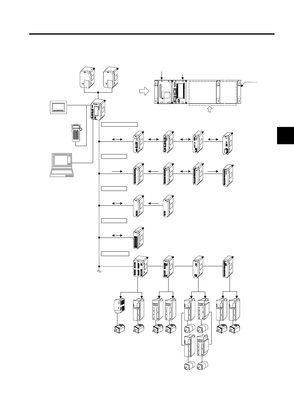
2.2 Basic System Configuration
2-43
2
2.2.2
Overall Configuration
* For connection with
Σ-II series servomotors, refer to A.6 Connection between
Σ
-II Series SER-
VOPACKs and MP920 Modules.
24-VDC input
power supply
PS-03
100/200-VAC input
power supply
PS-01
CPU-01
CPU-02
MEMOBUS
Panel
Teaching
pendant
TB350
MEMOBUS
Communications module
Digital I/O
Analog I/O
Expansion module
Servo module
Ehernet
communications
module
64-point input
module
(24 VDC)
Real-time
core
commuications
module
(4 Mbps)
DeviceNet
communications
module
Analog input
(4 channels)
Expansion I/O module
(up to 4 racks)
General-purpose
serial communications
module
(RS-232C
×2,
RS-485)
32-point input/
32-point output
module
(24 VDC)
4-channel
pulse inputs
64-point output
module
(24 VDC)
Analog output
(4 channels)
218IFA
217IF
215IF
260IF
AO-01
AI-01
LIO-01
CNTR-01
EXIO IF
DO-01
DI-01
SVB-01
PO-01
SVA-01A
SVA-02A
4 axes (max.)
speed control
2 axes control (max.)
(Speed) +
(Torque) control
MECHATROLINK
14 axes max.
4-channel pulse output
4 axes max.
SGDA- S
SGDB-
SGDM-
SGDM-
SGD- N
SGDB- AN
SGDH+
NS100
Pulse motor drives
and position control
servo drives
Programming device
Mounting
base
MB-01
or
MB-02
Optional modules
PS-03 or
PS-01
CPU-01 or
CPU-02
SW1
L.RST
RUN
INIT
TEST
MULTI
FLASH
M.RST
ON
OFF
ON
1
2
3
4
5
6
7
8
PORT2
PORT1
CN1
RLY OUT
BATTERY
RDY
PRT1
RUN
ALM
ERR
BAT
ALM
PRT2
DC24V
POWER
TB1
+24V
0V
FG
SG
*