Module connection examples, Important – Yaskawa MP920 User's Manual Design User Manual
Page 225
5 Modules
5.3.2 DO-01 Output Module
5-30
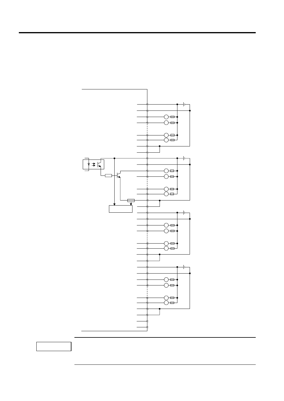
Module Connection Examples
An example of connections to the CN1 connector and an output circuit for the DO-01 Output
Module are shown below.
A fuse is inserted in the output common line of the DO-01 Module as a protective circuit. If the output
short-circuit is incomplete, there is a risk that the fuse may not blow. Insert a protective element, such
as a fuse, for each output as shown in the above illustration.
7
32
8
33
11
36
13
12
37
38
14
39
17
42
18
43
19
44
20
45
23
48
24
49
25
50
1
26
2
27
5
30
6
31
L
L
L
L
Output 1
Output 2
Output 7
Output 8
Output 9
Output 10
Output 15
Output 16
Output 17
Output 18
Output 23
Output 24
Output 25
Output 26
Output 31
Output 32
L
L
L
L
L
L
L
L
L
L
L
L
JEPMC-IO210
CN1 connector
pin numbers
+ -
24 VDC
+ -
24 VDC
+ -
24 VDC
+ -
24 VDC
Fuse
Fuse
Photocoupler
Blown fuse
detection circuit
.
.
.
.
.
.
.
.
.
.
.
.
IMPORTANT
- Tag Generator (30 pages)
- MP3300iec (82 pages)
- 1000 Hz High Frequency (18 pages)
- 1000 Series (7 pages)
- PS-A10LB (39 pages)
- iQpump Micro User Manual (300 pages)
- 1000 Series Drive Option - Digital Input (30 pages)
- 1000 Series Drive Option - CANopen (39 pages)
- 1000 Series Drive Option - Analog Monitor (27 pages)
- 1000 Series Drive Option - CANopen Technical Manual (37 pages)
- 1000 Series Drive Option - CC-Link (38 pages)
- 1000 Series Drive Option - CC-Link Technical Manual (36 pages)
- 1000 Series Drive Option - DeviceNet (37 pages)
- 1000 Series Drive Option - DeviceNet Technical Manual (81 pages)
- 1000 Series Drive Option - MECHATROLINK-II (32 pages)
- 1000 Series Drive Option - Digital Output (31 pages)
- 1000 Series Drive Option - MECHATROLINK-II Technical Manual (41 pages)
- 1000 Series Drive Option - Profibus-DP (35 pages)
- AC Drive 1000-Series Option PG-RT3 Motor (36 pages)
- Z1000U HVAC MATRIX Drive Quick Start (378 pages)
- 1000 Series Operator Mounting Kit NEMA Type 4X (20 pages)
- 1000 Series Drive Option - Profibus-DP Technical Manual (44 pages)
- CopyUnitManager (38 pages)
- 1000 Series Option - JVOP-182 Remote LED (58 pages)
- 1000 Series Option - PG-X3 Line Driver (31 pages)
- SI-EN3 Technical Manual (68 pages)
- JVOP-181 (22 pages)
- JVOP-181 USB Copy Unit (2 pages)
- SI-EN3 (54 pages)
- SI-ET3 (49 pages)
- MECHATROLINK-III (35 pages)
- EtherNet/IP (50 pages)
- SI-EM3 (51 pages)
- 1000-Series Option PG-E3 Motor Encoder Feedback (33 pages)
- 1000-Series Option SI-EP3 PROFINET (56 pages)
- PROFINET (62 pages)
- AC Drive 1000-Series Option PG-RT3 Motor (45 pages)
- SI-EP3 PROFINET Technical Manual (53 pages)
- A1000 Drive Option - BACnet MS/TP (48 pages)
- 120 Series I/O Modules (308 pages)
- A1000 12-Pulse (92 pages)
- A1000 Drive Software Technical Manual (16 pages)
- A1000 Quick Start (2 pages)
- JUNMA Series AC SERVOMOTOR (1 page)
- A1000 Option DI-101 120 Vac Digital Input Option (24 pages)