7 managing symbols, 1 symbols in drawings, 2 symbols in functions – Yaskawa MP920 User's Manual Design User Manual
Page 112
3 Basic System Operation
3.7.1 Symbols in Drawings
3-38
3.7
Managing Symbols
3.7.1
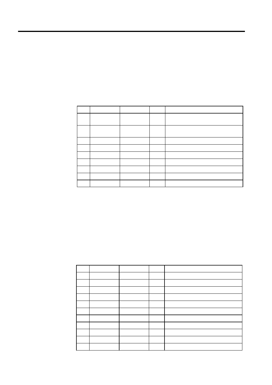
Symbols in Drawings
The symbols used in drawings are all managed with a symbol table, such as the one shown in
the table below. For details, refer to the Machine Controller MP900/MP2000 Series User’s
Manual: Ladder Programming (SIEZ-C887-1.2).
* If a program is written using data configurations such as arrays or indexed
data, define the size to be used in the data configuration.
For example, if the data is referenced as PIDDATA_1 and i varies in a
range of 0 to 9, define the size as 10.
3.7.2
Symbols in Functions
All symbols used in the functions are managed with the function symbol table shown in
Table 3.17. For details, refer to the Machine Controller MP900/MP2000 Series User’s Man-
ual: Ladder Programming (SIEZ-C887-1.2).
* If a program is prepared using data configurations such as arrays or
No.
Register No.
Symbol
Size *
Remarks
0
IB00000
STARTPBL
1
The register number is expressed as a hexa-
decimal number.
1
OB00000
STARTCOM
1
The register number is expressed as a hexa-
decimal number.
2
MW00000
SPDMAS
1
3
MB000010
WORK-DB
16
4
MW00010
PIDDATA
10
5
MW00020
LAUIN
1
6
MW00021
LAUOUT
1
:
N
Table 3.17 Function Symbol Table
No.
Register No.
Symbol
Size *
Remarks
0
XB000000
EXECOM
1
1
XW00001
INPUT
1
2
AW00001
P-GAIN
1
3
AB00000F
ERROR
1
4
YB000000
PIDEXE
1
5
YW00001
PIDOUT
1
6
ZB000000
WORKCOIL
4
7
ZW00001
WORK1
1
8
ZW00002
WORK2
1
:
N