2 processing flow when a system error occurs – Yaskawa MP920 User's Manual Design User Manual
Page 497
12.2 System Errors
12-7
12
12.2.2
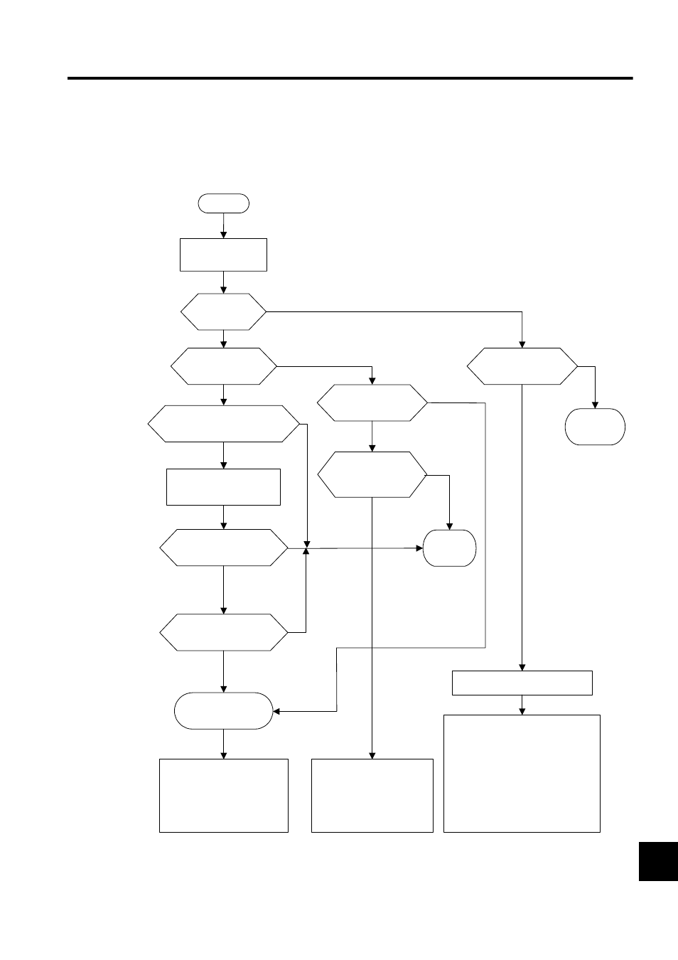
Processing Flow When a System Error Occurs
The following illustration shows the processing flow when a system error occurs.
* See Indicator Details in 12.1.3 Indicator Errors for more details on indicator patterns.
Classify error contents
based on the indicator
pattern.*
YES
NO
YES
NO
NO
YES
NO
YES
YES
User program error
Watchdog time error
YES
YES
NO
NO
YES
NO
Other
START
Classification =
Warning?
Classification =
Fatal error?
Serious failure
"RUN + ERR"
Hardware
failure
Check the contents of CPU
error status (SW00041).
Replace
battery.
ERR indicator flashing
Battery alarm
Hardware failure/watchdog
time error; only the ERR
indicator lights?
Turn the RUN switch
(DIP switch pin 2) OFF
and turn power back ON.
Online Stop Mode
Only RDY indicator lights?
Check the contents of
SW00050.
User program error
See 12.2.3 Processing Flow When
a User Program Error Occurs and
check the location where the error
occurred.
Program memory had not
been initialized.
Scan time setting error
Operation error (SB000418)
See User Operation Error Status in
12.2.4 System Register Configuration.
I/O error (SB000419)
See System I/O Error Status in
12.2.4 System Register Configuration.
Incorrect interrupt (SB00041A)
Hardware failure