Yaskawa MP920 User's Manual Design User Manual
Page 124
4 Motion Control
4.2.2 Speed Reference Output Mode
4-10
* 1. Valid only with an SVB-01 Module.
* 2. Valid only with an SVA-02A Module.
2. Set the motion parameters.
The following three methods can be used to set the setting parameters.
• Using the MPE720 Setting Parameter Window
• Using a ladder logic program
• Using a motion program
* Valid only with an SVA-02A Module.
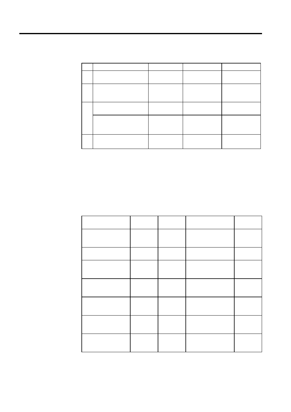
Table 4.1 Examples of Fixed Parameters
No.
Name
Setting Range
Meaning
Setting Example
7
Rated Motor Speed
Setting
1 to 32000
Rated motor speed
3000 r/min
8
Feedback Pulses per
Motor Rotation
4 to 65532
Number of pulses
before multiplica-
tion
2048 pulses/rev
9
D/A Output Voltage at
100% Speed
0.001 to 10.000
1 = 1 V
6.000 V
Feedback Pulses per
Motor Rotation
(for High-resolution)
*1
4 to 2147483647 1 = 1 pulse/rev
2048 pulses/rev
10 D/A Output Voltage at
100% Torque Limit
*2
0.001 to 10.000
0.001 = 0.001 V
1 = 1 V
3.000 V
Examples of Setting Parameters
Name
Register
No.
Setting
Range
Meaning
Setting
Example
Positive Torque Limit
Setting
(TLIMP)*
OW02
-32768 to
32767
1 = 0.01%
-10000
(-100.00%)
Positive Speed Limiter
Setting (NLIMP)
OW04
0 to 32767
1= 0.01%
13000
(130.00%)
Negative Speed
Limiter Setting
(NLIMN)
OW05
0 to 32767
1= 0.01%
13000
(130.00%)
Linear Acceleration
Time Constant
(NACC)
OW0C
0 to 32767
Linear acceleration time
constant (ms) at speed
pattern generation
1000
(1 second)
Linear Deceleration
Time Constant
(NDEC)
OW0D
0 to 32767
Linear deceleration time
constant (ms) at speed
pattern generation
1000
(1 second)
Filter Time Constant
Setting
(NNUM)
OW14
0 to 255
For simple S-curve
acceleration
0
Speed Reference
Setting
(NREF)
OW15
-32768 to
32767
Speed reference value
1= 0.01%
5000
(50.00%)