Cn1 connector – Yaskawa MP920 User's Manual Design User Manual
Page 241
5 Modules
5.3.4 CNTR-01 Counter Module
5-46
The CNTR-01 Module has a 5-V differential type pulse input connector with 4 channels and a 12-V
voltage type pulse input connector with 4 channels. Either 5-V differential or 12-V voltage must be
selected for each channel, so 4 channels in total per CNTR-01 Module can be operated.
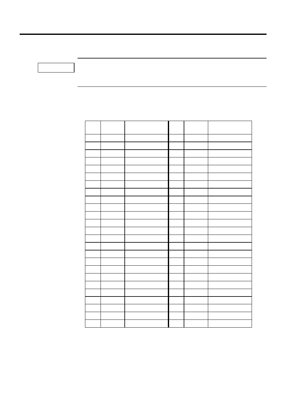
CN1 Connector
The following table shows the name and function of the CN1 connector pins.
Pin
No.
Signal
Name
Function
Pin
No.
Signal
Name
Function
1
26
2
27
3
+5PA1
+PI 5V phase-A 1
28
-5PA1
+PI 5V phase-A 1
4
+5PB1
+PI 5V phase-B 1
29
-5PB1
+PI 5V phase-B 1
5
+5PC1
+PI 5V phase-C 1
30
-5PC1
+PI 5V phase-C 1
6
GND
Ground
31
GND
Ground
7
32
8
33
9
+5PA2
+PI 5V phase-A 2
34
-5PA2
+PI 5V phase-A 2
10
+5PB2
+PI 5V phase-B 2
35
-5PB2
+PI 5V phase-B 2
11
+5PC2
+PI 5V phase-C 2
36
-5PC2
+PI 5V phase-C 2
12
GND
Ground
37
GND
Ground
13
38
14
+5PA3
+PI 5V phase-A 3
39
-5PA3
+PI 5V phase-A 3
15
+5PB3
+PI 5V phase-B 3
40
-5PB3
+PI 5V phase-B 3
16
+5PC3
+PI 5V phase-C 3
41
-5PC3
+PI 5V phase-C 3
17
GND
Ground
42
GND
Ground
18
43
19
44
20
+5PA4
+PI 5V phase-A 4
45
-5PA4
+PI 5V phase-A 4
21
+5PB4
+PI 5V phase-B 4
46
-5PB4
+PI 5V phase-B 4
22
+5PC4
+PI 5V phase-C 4
47
-5PC4
+PI 5V phase-C 4
23
GND
Ground
48
GND
Ground
24
49
25
50
IMPORTANT