3 torque reference output mode, Ladder logic program example, Overview – Yaskawa MP920 User's Manual Design User Manual
Page 126: Important
4 Motion Control
4.2.3 Torque Reference Output Mode
4-12
Ladder Logic Program Example
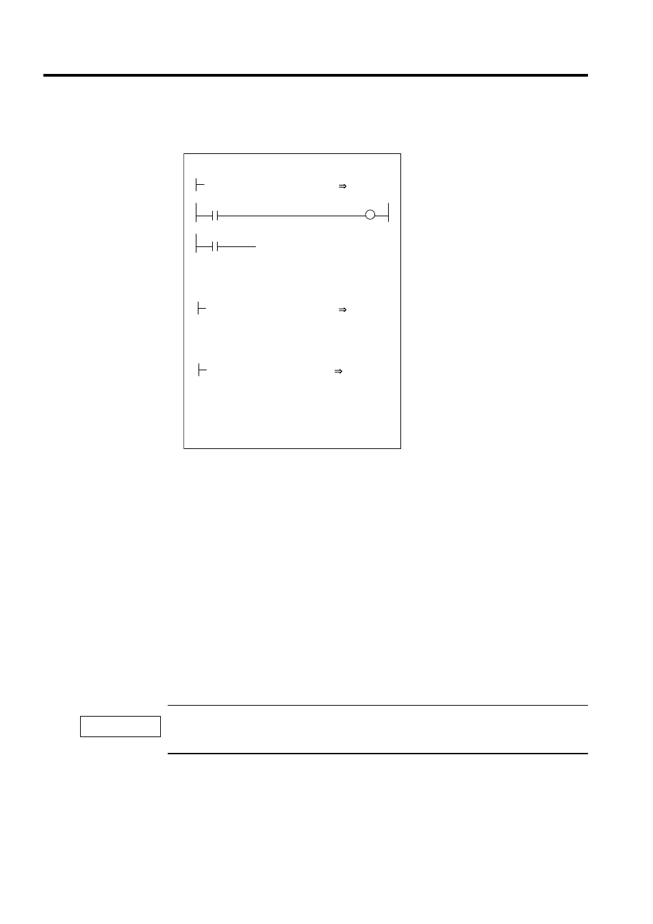
Fig. 4.2 RUN Commands (DWG H01)
The example in the above illustration has been greatly simplified. In actual operation, each
register can be controlled from the user program.
4.2.3
Torque Reference Output Mode
Overview
This mode is used to generate a constant torque, regardless of the speed.
Select this mode to keep the metal mold of a plastic molding machine, such as an injection
molding machine, at a constant pressure.
When the torque reference output mode is selected, the specified torque reference and speed
limit reference are output by the servo driver.
This mode can be used only with an SVA-02A Module (2-axis).
The torque reference output mode can be used only with SVA-02A Module. It cannot be used with
SVA-01A, SVB-01, or PO-01 Module.
0
Set the speed reference output mode to ON.
Driver RUN command (RUN)
When IB00104 turns ON, the speed
reference output mode starts.
When the acceleration command (IB00105)
turns ON, a speed reference of 50% is
output for the acceleration time constant
(ACC).
When IB00105 turns OFF, the deceleration
time constant (DEC) decelerates to a stop
(a speed reference of 0% is output).
IFON
ELSE
IEND
DEND
RUN
OBC0010
RUNPB
IB00104
ACCEL
IB00105
500
NREF
OWC015
NREF
OWC015
H0101
RUNMOD
OWC000
IMPORTANT