Yaskawa MP920 User's Manual Design User Manual
Page 444
9.2 Setting Up a Multi-CPU System
9-17
9
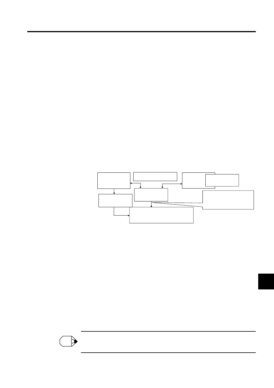
e) Motion Module Definitions
Set the motion fixed parameters to the same values for CPU Module 1 and CPU
Module 2. The settings of CPU Module 1 will be written to the fixed parameters of
the Motion Module, but set the same values for both CPU Modules for reference by
the internal processing.
Manually setting temporary motion setting parameters using the MPE720 is possible
for either CPU Module 1 or CPU Module 2.
When accessing data from user application programs, use the Control CPU Module.
If the Sub CPU Module is used, do not access the data immediately after the start of
the scan and assign one CPU Module to write the setting parameters for each axis to
avoid malfunctions caused by access conflicts. Set the synchronized scan to the high-
speed scan and run the application program in the high-speed scan. Set the group def-
initions required for the user application program in each CPU Module. Be sure that
each axis is allocated in only one CPU Module.
The values of the setting parameters saved in the CPU Module 1 will be used as the
initial values at startup. Therefore, save the settings in the CPU Module 1.
Fig. 9.12 Motion Module Data Configuration
f) Communications Module Definitions
Set the transmission parameters to the same values in CPU Module 1 and CPU Mod-
ule 2. If the settings are different, the transmission parameters of the Control CPU
Module will be used.
Do not allocate any outputs (O registers) in the link map and I/O map for the Sub
CPU Module. Allocate outputs only for the Control CPU Module. When allocating
the inputs (I registers) for the Sub CPU Module, match the settings to those of the
Control CPU Module. In this way, the input data can be referenced.
The values of the input data (I registers) is not concurrent between words, and new
and old data may be mixed. For an application that requires concurrency between
words, program the Modules so that the Sub CPU Module reads the I registers that
were read and stored in the shared memory by the Control CPU Module.
For message communications using the MSG-SND and MSG-RCV functions, specify CIR =
1 or 2 for the CPU Module 1 port 1 or 2, CIR = 3 or 4 for the CPU Module 2 port 1 or 2.
CPU Module 1
individual application
program
Fixed parameters
(CPU Module 2)
High-seed scan synchronization
Setting parameters
(CPU Modules 1 and
2)
Motion Modules (SVA, SVB, etc.)
CPU Module
2 individual
application
program
Fixed parameters
(CPU Module 2)
The latest settings will be used.
Outputs at the timing of the
Control CPU Module
(CPU Module 1).
INFO