Pulse output module (po-01) – Yaskawa MP920 User's Manual Design User Manual
Page 43
2.1 Specifications
2-17
2
Pulse Output Module (PO-01)
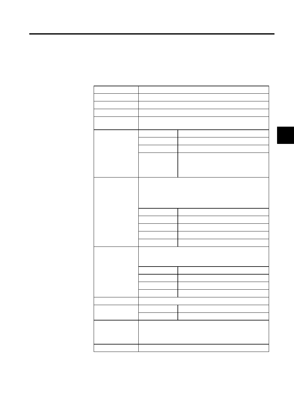
Table 2.15 shows the hardware specifications of the PO-01 Pulse Output Module.
Table 2.15 Hardware Specifications of the PO-01 Pulse Output Module
Item
Specifications
Name
Pulse Output Module
Model Number
JEPMC-PL210
Description
PO-01
No. of Controlled
Axes
4
Pulse Output
Methods
Sign + pulse, pulse
Frequency
500 kpps max. (software switching)
Interface
5-V differential output
Other functions
Can be switched between positive and negative
logic by software.
Two emergency stopping method (immediate
stop/deceleration to a stop)
Digital Inputs
Photocoupler insulation, current sourcing mode input 5 points
× 4
channels
DI_0: Individual power supply
5 V/5 mA, 12 V/12 mA, or 24 V/5 mA
DI_1 to DI_4: Common power supply, 0.5 ms filter, 24 V/5 mA
Allocation example
DI_0
Zero point
DI_1
Dog signal/general-purpose
DI_2
Limit 1
DI_3
Limit 2
DI_4
Emergency stop/Deceleration to a stop
Digital Outputs
24-V open-collector (current sinking mode output)
4 points
× 4 channels
Photocoupler insulation, 100 mA max.
Allocation example
DO_0
Excitation ON
DO_1
General-purpose
DO_2
General-purpose
DO_3
General-purpose
Indicator
Module status 7-segment LED indicator (green)
Connectors
CN1
Axis-1 and -2 connector 10250-52A2JL
CN2
Axis-3, and -4 connector 10250-52A2JL
Hot Swapping (In-
sert/Remove while
power is being sup-
plied)
Not allowed.
Dimensions (mm)
40
× 130 × 105 (W × H × D)