5 i/o and registers in functions – Yaskawa MP920 User's Manual Design User Manual
Page 110
3 Basic System Operation
3.6.5 I/O and Registers in Functions
3-36
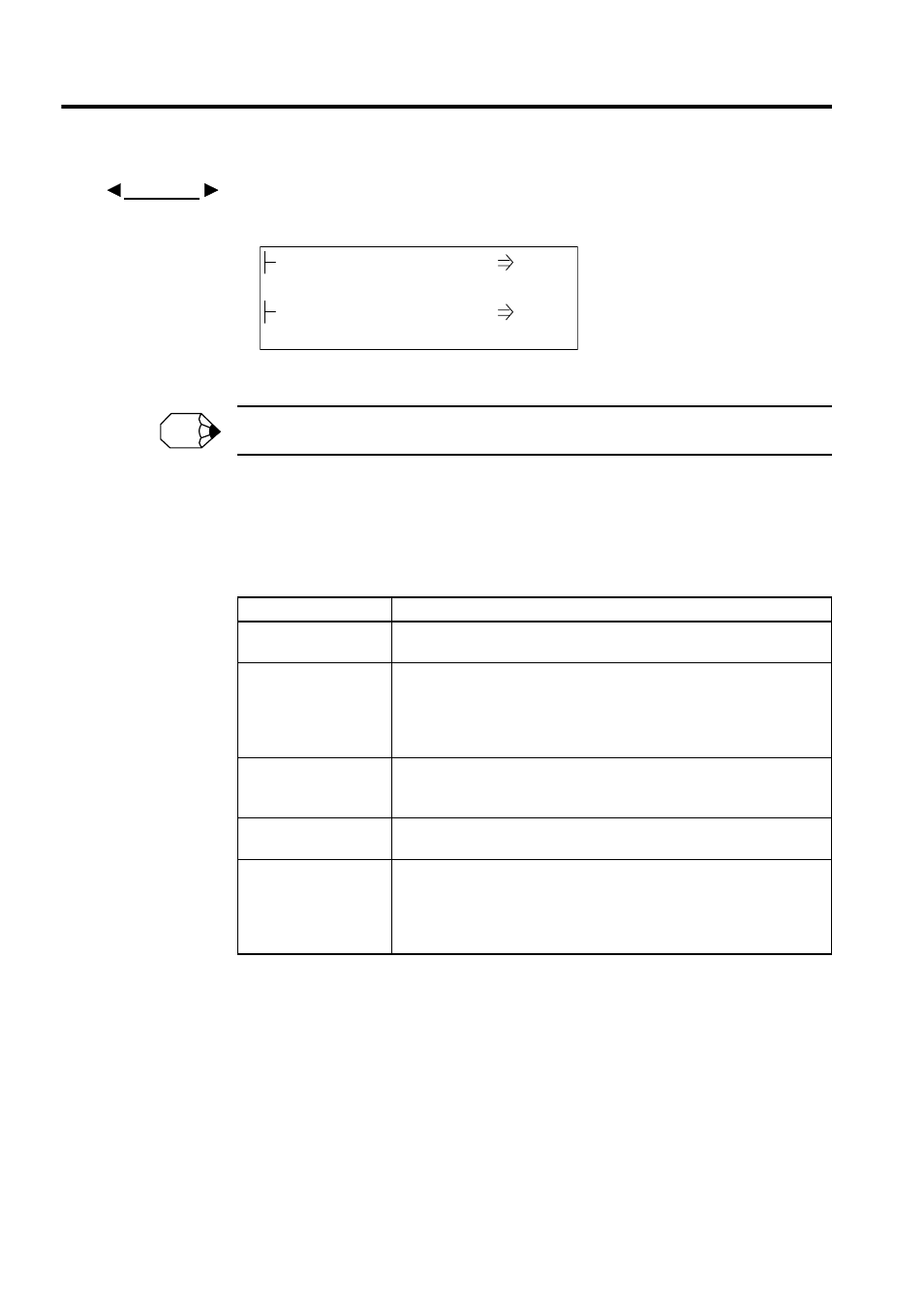
Programming Example Using Subscripts
The programming code shown in Fig. 3.11 sets the sum of 100 registers from MW00100 to MW00199
in MW00200 using subscript J.
Fig. 3.11 Programming Example Using a Subscript
Subscripts I and J cannot be used in motion programs.
3.6.5
I/O and Registers in Functions
Table 3.16 shows the I/O and registers referenced in functions.
EXAMPLE
00000
FOR J = 00000 to 00099 by 00001
MW00200 + MW00100j
FEND
MW00200
MW00200
INFO
Table 3.16 Correspondence Between I/O and Registers in Functions
Function I/O
Function Register
Bit inputs
The bit numbers increase continuously from XB000000 in order of the bit
inputs: XB000000, XB000001, XB000002,
……, XB00000F
Integer, double-length
integer, and real num-
ber inputs
The register numbers increase continuously from XW, XL, and XF00001 in
order of the integer, double-length integer, and real number inputs:
XW00001, XW00002, XW00003,
……, XW00016
XL00001, XL00003, XL00005,
……, XL00015
XF00001, XF00003, XF00005,
……, XF00015
Address inputs
The address input values correspond to register numbers 0 of the external
register:
Input value = MA00100: MW00100 = AW00000, MW00101 = AW00001...
Bit outputs
The bit number increases consecutively from YB000000 in order of bit out-
puts: (YB000000, YB000001, YB000002, YB00000F)
Integer, double-length
integer, and real num-
ber outputs
The register numbers increase continuously from YW, YL, and YF00001 in
order of the integer, double-length integer, and real number outputs.
YW00001, YW00002, YW00003, ......, YW00016
YL00001, YL00003, YL00005, ......, YL00015
YF00001, YF00003, FY00005, ......, YF00015