Four-axis servo module (sva-01a) – Yaskawa MP920 User's Manual Design User Manual
Page 40
2 MP920 Specifications and System Configuration
2.1.2 Hardware Specifications
2-14
Four-axis Servo Module (SVA-01A)
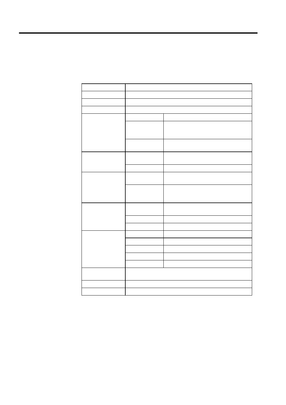
Table 2.12 shows the hardware specifications of the SVA-01A Analog Servo Module.
Table 2.12 Hardware Specifications of the SVA-01A 4-axis Servo Module
Item
Specifications
Name
Four-axis Servo Module
Model Number
JEPMC-MC200A
Description
SVA-01A
Servo Interface
Pulse input circuit
5 V differential, maximum 1 MHz input
Pulse input method Phase-A/B/C pulses input (can be selected from
×1, ×2, and ×4), A/B mode, sign mode, up/down
mode
Pulse counter latch
DI (can be selected from zero point and external
latch signal)
Analog Outputs
D/A speed
references
Sign + 15 bits, 4 points
Output range
0 to
±11 V
Digital Inputs
Servo DI
3 points
× 4 channels, 4 mA at 24 VDC,
source input SV ALM, SRDY, BRK
External DI
6 points
× 4 channels, 4 mA at 24 VDC,
source input OTF, OTR, DEC, ZERO, EXT, RI
(ZERO and EXT can be latched.)
Digital Outputs
Servo DO
6 points
SV ON, ALM RST, P_CON, SEN, OTR, OTF
External DO
2 points
× 4 channels, 24 VDC ±2%
Output current
100 mA BRK, RO
Connectors
CN1
Servo connector 1 10236-52A2JL
CN2
Servo connector 2 10236-52A2JL
CN3
Servo connector 3 10236-52A2JL
CN4
Servo connector 4 10236-52A2JL
CN5
External interface connector 10250-52A2JL
Current
Consumption
720 mA
Indicator
Module status 7-segment LED indicator (green)
Dimensions (mm)
80
× 130 × 105 (W × H × D)