2 test system configuration, Important – Yaskawa MP920 User's Manual Design User Manual
Page 333
6.1 Overview
6-3
6
6.1.2
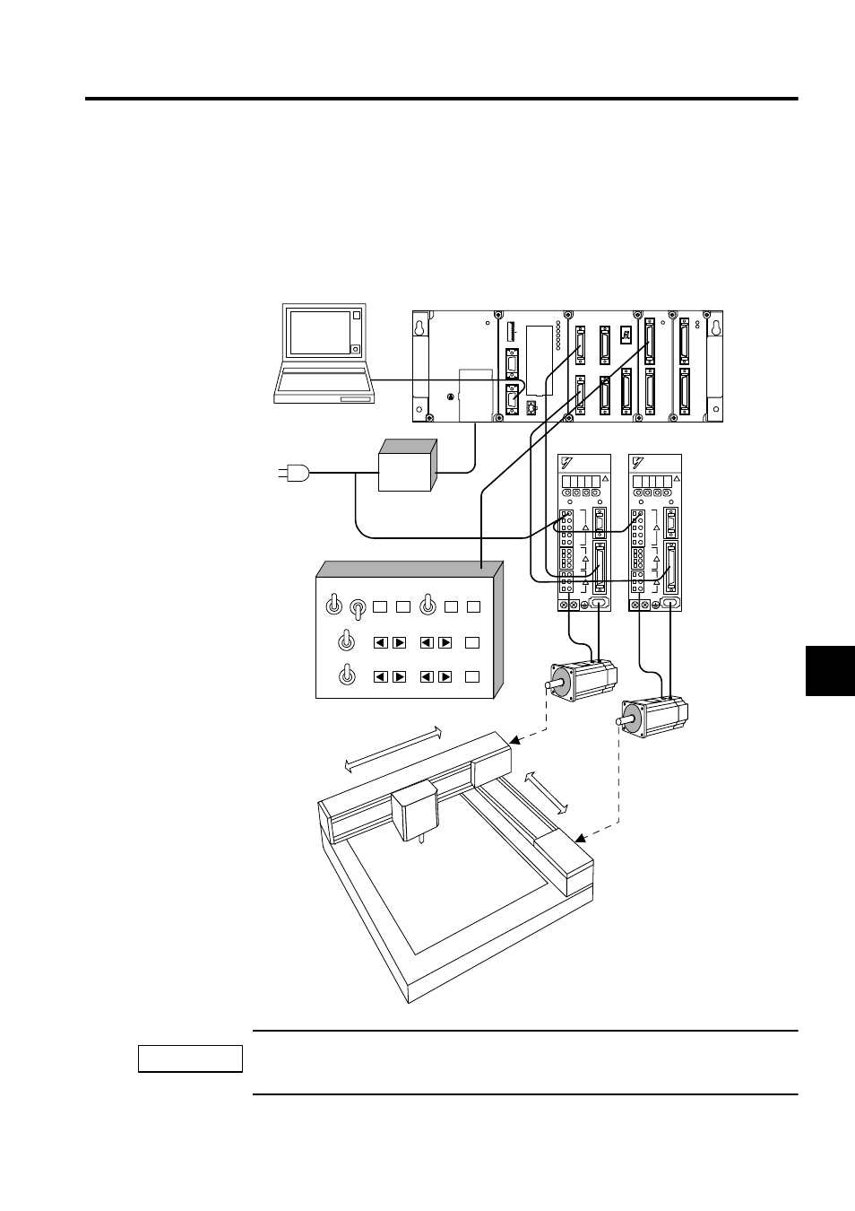
Test System Configuration
The Test System is a simple system for explaining MP920 system startup. The Test System
is different from the one that is used for actual applications.
The following illustration shows the Test System configuration.
Because this system is used for testing, there is no emergency stop circuit, and no servo amp power
OFF circuit for overtravel. For actual applications, be sure to insert the correct emergency stop circuits.
Servo ON
Servo ON
OFF
Automatic Manual
JOG
ZRN
Start
Reset
Pause
stop
Alarm
reset
STEP
Axis 1:
Axis 2:
OFF
JOG
ZRN
STEP
Servomotors
Switch box
X
Y
X-Y table
AVR
SW1
L.RST
RUN
INIT
TEST
MULTI
FLASH
M.RST
ON
OFF
ON
1
2
3
4
5
6
7
8
PORT2
PORT1
CN1
RLY OUT
BATTERY
RDY
PRT1
RUN
ALM
ERR
BAT
ALM
PRT2
MP920 CPU-01
SVA-01
CN1
CN3
CN2
CN4
STATUS
CN5
DI-01
CN1
CN2
RUN
DO-01
CN1
CN2
RUN
FUSE
PS-03
DC24V
POWER
TB1
+24V
0V
FG
SG
PS-03
CPU-01
SVA-01A
DI-01 DO-01
Programming Device
SGDM SERVOPACKs
24 VDC
100 VAC
Emergency
IMPORTANT
- Tag Generator (30 pages)
- MP3300iec (82 pages)
- 1000 Hz High Frequency (18 pages)
- 1000 Series (7 pages)
- PS-A10LB (39 pages)
- iQpump Micro User Manual (300 pages)
- 1000 Series Drive Option - Digital Input (30 pages)
- 1000 Series Drive Option - CANopen (39 pages)
- 1000 Series Drive Option - Analog Monitor (27 pages)
- 1000 Series Drive Option - CANopen Technical Manual (37 pages)
- 1000 Series Drive Option - CC-Link (38 pages)
- 1000 Series Drive Option - CC-Link Technical Manual (36 pages)
- 1000 Series Drive Option - DeviceNet (37 pages)
- 1000 Series Drive Option - DeviceNet Technical Manual (81 pages)
- 1000 Series Drive Option - MECHATROLINK-II (32 pages)
- 1000 Series Drive Option - Digital Output (31 pages)
- 1000 Series Drive Option - MECHATROLINK-II Technical Manual (41 pages)
- 1000 Series Drive Option - Profibus-DP (35 pages)
- AC Drive 1000-Series Option PG-RT3 Motor (36 pages)
- Z1000U HVAC MATRIX Drive Quick Start (378 pages)
- 1000 Series Operator Mounting Kit NEMA Type 4X (20 pages)
- 1000 Series Drive Option - Profibus-DP Technical Manual (44 pages)
- CopyUnitManager (38 pages)
- 1000 Series Option - JVOP-182 Remote LED (58 pages)
- 1000 Series Option - PG-X3 Line Driver (31 pages)
- SI-EN3 Technical Manual (68 pages)
- JVOP-181 (22 pages)
- JVOP-181 USB Copy Unit (2 pages)
- SI-EN3 (54 pages)
- SI-ET3 (49 pages)
- MECHATROLINK-III (35 pages)
- EtherNet/IP (50 pages)
- SI-EM3 (51 pages)
- 1000-Series Option PG-E3 Motor Encoder Feedback (33 pages)
- 1000-Series Option SI-EP3 PROFINET (56 pages)
- PROFINET (62 pages)
- AC Drive 1000-Series Option PG-RT3 Motor (45 pages)
- SI-EP3 PROFINET Technical Manual (53 pages)
- A1000 Drive Option - BACnet MS/TP (48 pages)
- 120 Series I/O Modules (308 pages)
- A1000 12-Pulse (92 pages)
- A1000 Drive Software Technical Manual (16 pages)
- A1000 Quick Start (2 pages)
- JUNMA Series AC SERVOMOTOR (1 page)
- A1000 Option DI-101 120 Vac Digital Input Option (24 pages)