Dip switch (sw1), 10base -t port (cn1) – Yaskawa MP920 User's Manual Design User Manual
Page 313
5 Modules
5.6.1 218 I/F Communications Module (218IFA)
5-118
The LED indicators indicate error or failure occurred in the Module as shown below.
Note: The number in parentheses ( ) indicates the number of blinkings.
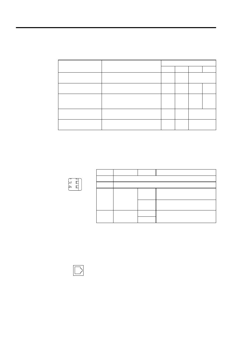
DIP Switch (SW1)
The SW1 is used for self-diagnosis.
All the pins are set by default to OFF (to the right).
* Default IP address: 192.168.1.1
Default engineering port number: 10000 (UDP)
At the initial start up, the 218IFA Module can use only engineering com-
munications function with MPE720.
10BASE -T Port (CN1)
LED Indicators When Error/Failure Occurs
Error/Failure
Details of Error/Failure
LED Indicators
RUN
ERR
TX
RX
PROM
checksum error
PROM checksum error was detected
during online self-diagnosis.
Unlit
Blink-
ing (1)
Depends on the
conditions.
SRAM error in Module
A hardware fault was detected during
online self-diagnosis.
Unlit
Blink-
ing (2)
Unlit
Unlit
CPU
interface error
An error in the data transmission with
CPU was detected during online self-
diagnosis.
Unlit
Blink-
ing (3)
Unlit
Unlit
Transmission error
Transmission data error
Lit
Lit
Depends on the
conditions.
Watchdog timeout error
Watchdog timeout
Unlit
Lit
Depends on the
conditions.
Pins
Name
Setting
Operation
−
Unused
−
Unused
INIT
Initial startup
ON
Starts up with the default IP address
and engineering port number.
*
OFF
Starts up with the IP address and engi-
neering port number set on MPE720.
TEST
TEST
ON
Executes self-diagnosis when started
with this pin set to ON.
OFF
The CN1 is used to connect the 218IFA Module and the 10Base-T
Ethernet.
No standard cable available
SW1
INIT
TEST
OFF
ON