Battery, Connector specifications, Connector pin layour (serial ports) – Yaskawa MP920 User's Manual Design User Manual
Page 208
5.2 CPU Modules
5-13
5
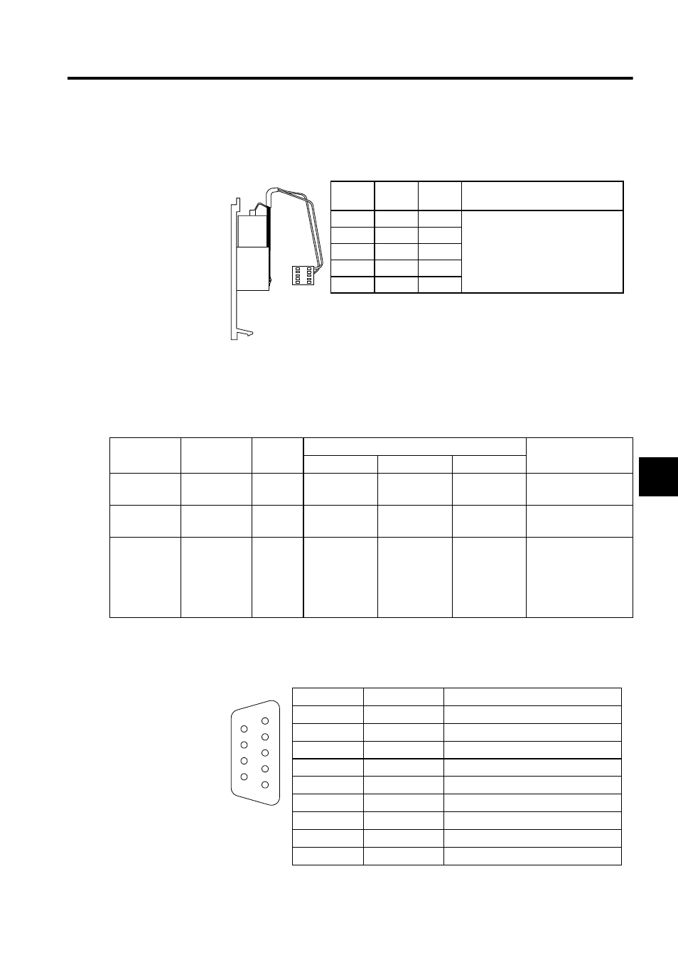
Battery
The battery is used as backup power supply for the SRAM.
Connector Specifications
The following table shows the specifications of the connectors used to connect the CPU-01
Module.
Connector Pin Layour (Serial Ports)
The pin layout of the serial port 1 and 2 is shown below.
Pin
Signal
Name
I/O
Remarks
1
GND
I
Battery Connector
Battery: ZZK000062 Battery
(ER6VC Lithium Battery
from Toshiba)
2
BAT
I
3
BAT
I
4
(NC)
I
5
GND
I
15
JAE
Name
Connector
Name
No. of
Pins
Connector Model
Cable Model
Module
Cable-end
Manufacturer
Serial Port 1
PORT1
9
D-sub,9-pin
female
D-sub,9-pin
male
JEPMC-W5310-
JEPMC-W5311-
Serial Port 2
PORT2
9
D-sub,9-pin
female
D-sub,9-pin
male
JEPMC-W5310-
JEPMC-W5311-
Status Output
Terminals
CN1
2
SL3.5-2-90F
BL3.5 /
2F-AU
The CN1 connector is
provided on the CPU-
01 Module. The con-
nection cable must be
prepared by the cus-
tomer.
Weidmuller
..
Pin Layout at
Connection Side
Pin No.
Description
Signal Name
1
FG
Protective grounding
2
TXD
Send data
3
RXD
Receive data
4
RTS
Request to send
5
CTS
Clear to send
6
DSR
Data set ready
7
GND
Signal grounding
8
−
−
9
DTR
Data terminal ready
5
4
3
2
1
9
8
7
6