3 215if communications module (215if), Led indicators – Yaskawa MP920 User's Manual Design User Manual
Page 320
5.6 Communications Modules
5-125
5
5.6.3
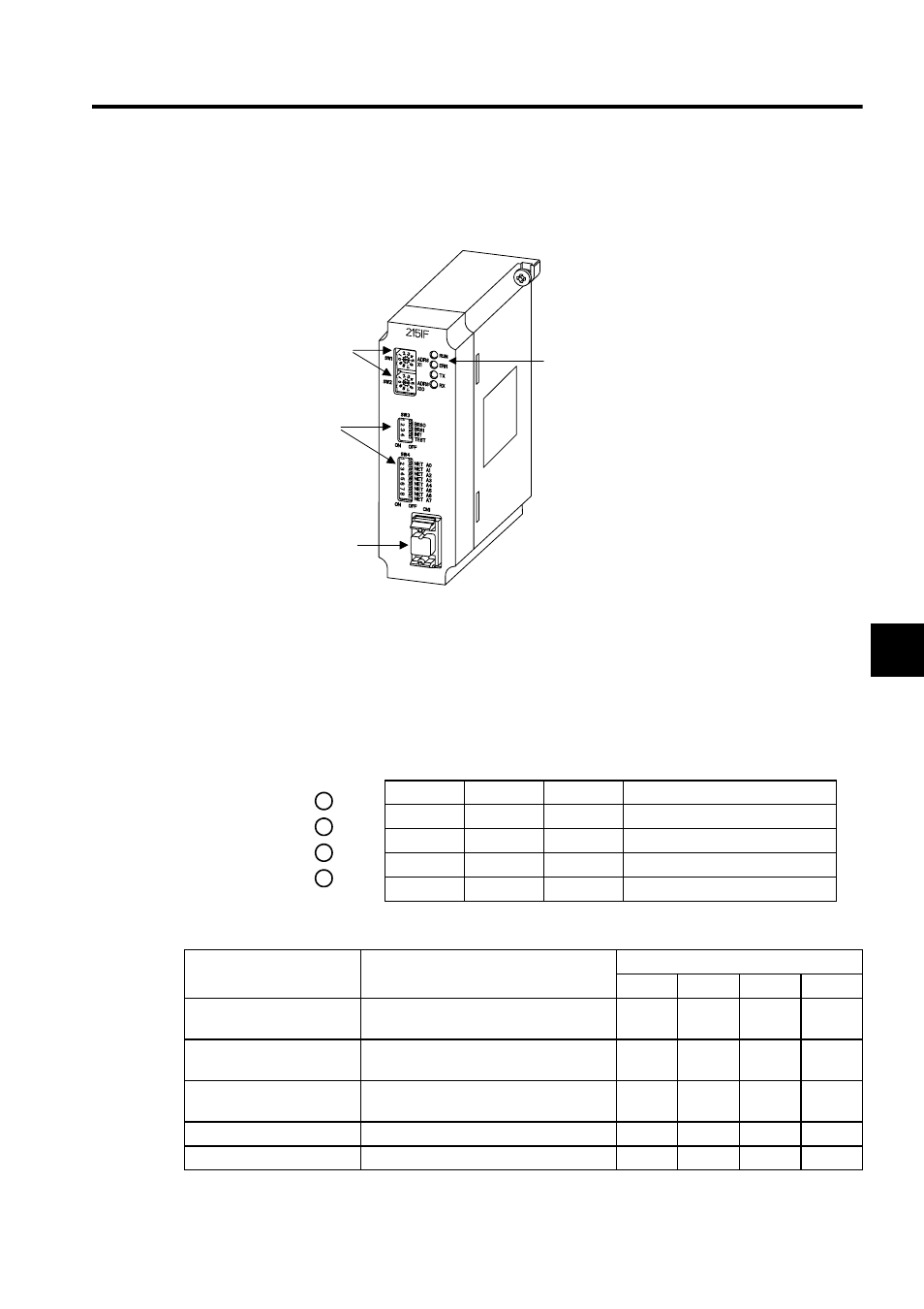
215IF Communications Module (215IF)
The following illustration shows the appearance of the 215IF Communications Module.
The details of each part of the 215IF Module are described below.
LED Indicators
While the 215IF Module is operating normally, the RUN LED indicator is lit and the ERR
LED indicator is unlit. When a failure occurs, the RUN lights off and the ERR lights up or
blinks. The TX or RX LED indicator is lit while the 215IF Module is sending or receiving
data.
The LED indicators indicate error or failure occurred in the Module as shown below.
Note: The number in parentheses ( ) indicates the number of blinkings.
Indicator
Name
Color
Status When Lit
RUN
RUN
Green
Normally operating
ERR
ERROR
Red
Failure occurrence (lights or blinks)
TX
215 TX
Green
215IF sending data
RX
215 RX
Green
215IF receiving data
Rotary
switches
DIP
switches
215IF port
CN1
LED indicators
RUN
ERR
TX
RX
Error/Failure
Details of Error/Failure
LED Indicators
RUN
ERR
TX
RX
PROM
checksum error
PROM checksum error was detected dur-
ing online self-diagnosis.
Unlit
Blinking
(1)
Unlit
Unlit
Hardware error in Module
A hardware failure was detected during
online self-diagnosis.
Unlit
Blinking
(2)
Unlit
Unlit
CPU interface error
A data transmission error with the CPU
was detected during online self-diagnosis.
Unlit
Blinking
(3)
Unlit
Unlit
Transmission error
A transmission error was detected.
Lit
Lit
Lit
Lit
Watchdog timeout error
Watchdog timeout
Unlit
Lit
Unlit
Unlit