Yaskawa MP920 User's Manual Design User Manual
Page 549
Appendix A
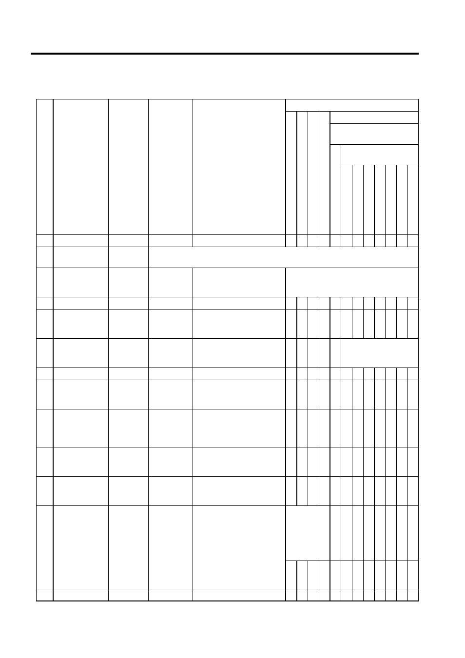
A.3.3 Motion Monitor Parameters
A-34
33
Not used
IL20
−
−
35
Alarms
(ALARM)
IL22
Reports alarm information.
37
Servo Driver
Alarm Code
(SVALARM)
IW24
-32768 to
32767
Error code when an absolute
position read error occurs
Valid when an absolute position read error
occurs
38
Not used
IW25
−
−
39
Speed Reference
Output Monitor
(RVMON)
IL26
-2
31
to 2
31
-1
1 = 1 reference unit/H scan
(For system use)
√ √ √ √ √ √ √
41
Position Buffer
Read Data
(CNMON)
IL28
-2
31
to 2
31
-1
Position buffer data
Valid when position
buffer read
(OB21F) is ON.
43
Not used
IL2A
−
−
45
Integral Output
Monitor
(YIMON)
IL2C
-2
31
to 2
31
-1
√
√ √ √ √ √ √ √ √ √
47
Calculated Ref-
erence Coordi-
nate System
Position (POS)
IL2E
-2
31
to 2
31
-1
1 = 1 reference unit
√ √ √ √ √ √ √
49
Primary Lag
Monitor
(LAGMON)
IL30
-2
31
to 2
31
-1
(PI output value - primary lag
output value)
√
√ √ √ √ √ √
√ √
51
Position Loop
Output Monitor
IL32
-2
31
to 2
31
-1
Position loop output value
(value prior to adding the cal-
culated feed forward value)
√
√ √ √ √ √ √
√ √
53
Position
Monitor 2
(APOS2)
IL34
-2
31
to 2
31
-1
Depends on Position Moniter
2 Unit Selection
(OB2D3).
1. OB2D3 = 0
(Reference unit selected)
1 = 1 reference unit
2. OB2D3 = 1
(Pulses selected)
1 = 1 pulse
(OB00
is ON) with
motion com-
mand code
enabled
selected.
√ √ √ √ √ √ √
√ √ √ √
55
Not used
IW36
−
−
(cont’d)
No.
Name
Register
Number
Setting
Range
Meaning
Control Mode Where Data Is Valid
Zero Point Return Mode
S
pee
d Control Mode
To
rq
ue Control
Mod
e
Pha
se C
ontrol
Mode
Position Control Mode
Motion Command
Code (OB008)
Motion
C
omma
nd
Disab
led
Motion Command
Code (OW20)
Positioning
External
Posi
tion
Zero Poin
t Return
Interpol
ation
La
tch
F
eed
St
ep