Tsi fpga – Artesyn ARTM-831X Installation and Use (June 2014) User Manual
Page 270
TSI FPGA
ARTM-831X Installation and Use (6806800M76E)
270
15
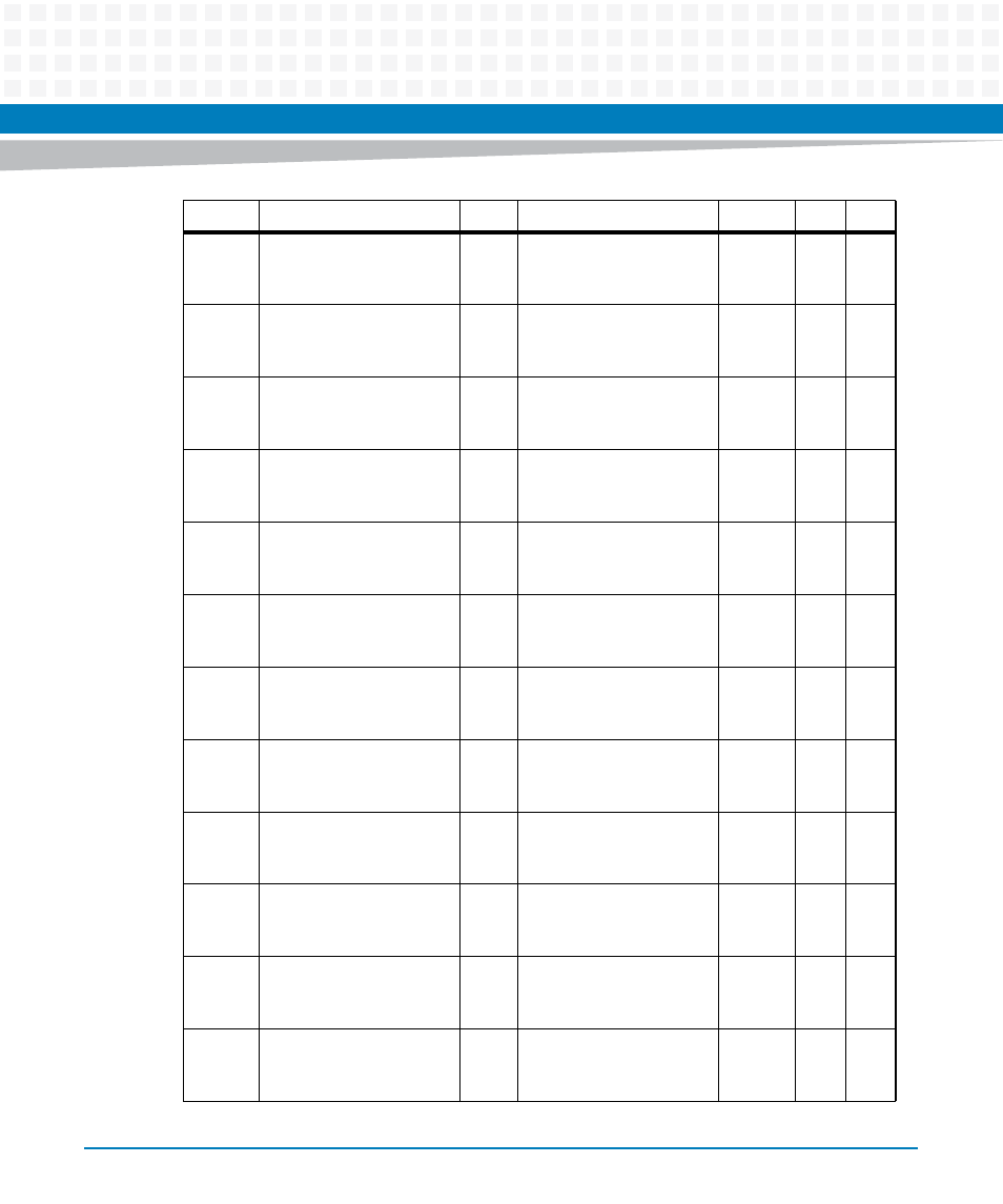
Xrt86Chp1RcvLoS7
R
0b1: Xrt86Chp1RcvLoS7,
Chip 1 receiver Line 7
indicates loss of signal
0b0
F
F
14
Xrt86Chp1RcvLoS6
R
0b1: Xrt86Chp1RcvLoS6,
Chip 1 receiver Line 6
indicates loss of signal
0b0
F
F
13
Xrt86Chp1RcvLoS5
R
0b1: Xrt86Chp1RcvLoS5,
Chip 1 receiver Line 5
indicates loss of signal
0b0
F
F
12
Xrt86Chp1RcvLoS4
R
0b1: Xrt86Chp1RcvLoS4,
Chip 1 receiver Line 4
indicates loss of signal
0b0
F
F
11
Xrt86Chp1RcvLoS3
R
0b1: Xrt86Chp1RcvLoS3,
Chip 1 receiver Line 3
indicates loss of signal
0b0
F
F
10
Xrt86Chp1RcvLoS2
R
0b1: Xrt86Chp1RcvLoS2,
Chip 1 receiver Line 2
indicates loss of signal
0b0
F
F
9
Xrt86Chp1RcvLoS1
R
0b1: Xrt86Chp1RcvLoS1,
Chip 1 receiver Line 1
indicates loss of signal
0b0
F
F
8
Xrt86Chp1RcvLoS0
R
0b1: Xrt86Chp1RcvLoS0,
Chip 1 receiver Line 0
indicates loss of signal
0b0
F
F
7
Xrt86Chp0RcvLoS7
R
0b1: Xrt86Chp0RcvLoS7,
Chip 2 receiver Line 7
indicates loss of signal
0b0
F
F
6
Xrt86Chp0RcvLoS6
R
0b1: Xrt86Chp0RcvLoS6,
Chip 2 receiver Line 6
indicates loss of signal
0b0
F
F
5
Xrt86Chp0RcvLoS5
R
0b1: Xrt86Chp0RcvLoS5,
Chip 2 receiver Line 5
indicates loss of signal
0b0
F
F
4
Xrt86Chp0RcvLoS4
R
0b1: Xrt86Chp0RcvLoS4,
Chip 2 receiver Line 4
indicates loss of signal
0b0
F
F
Bit
Acronym
Type
Description
Default
Pwr
Soft
- ARTM-9405 16x10GbE Installation and Use Guide (May 2014) (64 pages)
- ATCA 7370 / ATCA 7370-S Installation and Use (January 2015) (256 pages)
- ATCA 7370 / ATCA 7370-S Installation and Use (September 2014) (254 pages)
- ATCA-7350 - Integrating with Workbench User Guide (September 2014) (34 pages)
- ATCA-7350 Installation and Use (September 2014) (208 pages)
- ATCA-7365-CE Installation and Use (Jan 2015) (300 pages)
- ATCA-7365-CE Installation and Use (May 2014) (294 pages)
- ATCA-7365-CE Installation and Use (May 2014) (306 pages)
- ATCA-7368 Installation and Use (June 2014) (222 pages)
- ATCA-7475 Installation and Use (October 2014) (284 pages)
- ATCA-7480 Installation and Use (April 2015) (330 pages)
- ATCA-8330 Installation and Use (April 2015) (236 pages)
- ATCA-8320 Installation and Use (May 2014) (456 pages)
- ATCA-9305 User's Manual (May 2014) (270 pages)
- ATCA-9405 Installation and Use (October 2014) (168 pages)
- ATCA-F120 Installation and Use (August 2014) (122 pages)
- ATCA-F140 Installation and Use (September 2014) (138 pages)
- ATCA-MF106 Installation and Use (September 2014) (86 pages)
- Centellis-4440/AXP1440 Installation and Use (September 2014) (208 pages)
- Centellis 4410 (AXP-1410) Installation and Use (July 2014) (202 pages)
- Centellis 2100 Release 3.0 Installation and Use (March 2015) (192 pages)
- Centellis 2100 Release 3.0 Installation and Use (March 2015) (176 pages)
- Centellis 2000 User Card-10GE Installation and Use (May 2014) (54 pages)
- Centellis 2000 User Card-10GE with Telco Alarm Installation and Use (May 2014) (60 pages)
- COMX-CAR-210 Installation and Use (August 2014) (76 pages)
- COMX-P1022 Installation and Use (July 2014) (84 pages)
- COMX-P2020 Installation and Use (February 2015) (100 pages)
- COMX-CORE Series Installation and Use (August 2014) (128 pages)
- COMX-P2020 Installation and Use (July 2014) (100 pages)
- COMX-P4080-2G-ENP2 Installation and Use (August 2014) (70 pages)
- COMX-P4080 Installation and Use (August 2014) (126 pages)
- COMX-P40x0 ENP2 Installation and Use (August 2014) (130 pages)
- COMX-P40x0 ENP2 Installation and Use (January 2015) (140 pages)
- iVPX7225 RTM Installation and Use (April 2015) (56 pages)
- MITX-430/MITX-440-DVI-2E Installation and Use (August 2014) (118 pages)
- CPCI-6200 Installation and Use (May 2015) (234 pages)
- SCP-MITX-CORE-820-SM Installation and Use (August 2014) (132 pages)
- iVPX7225 Installation and Use (April 2015) (168 pages)
- MVME2502 Installation and Use (August 2014) (150 pages)
- MVME2502 Installation and Use (December 2014) (166 pages)
- MVME2500 VxWorks 6.8 AMP User Guide (August 2014) (40 pages)
- MVME2500 VxWorks 6.8 User Guide (April 2014) (44 pages)
- MVME3100 Single Board Computer Installation and Use (June 2014) (156 pages)
- MVME4100 Single Board Computer Installation and Use (June 2014) (136 pages)