26 artm telecom clock monitor registers, Table 8-52, Supervised artm telecom clocks reference list – Artesyn ARTM-831X Installation and Use (June 2014) User Manual
Page 147: Table 8-53, 289preselected telecom clocks reference list, Base artm fpga
Base ARTM FPGA
ARTM-831X Installation and Use (6806800M76E)
147
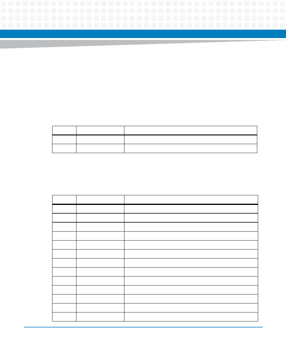
8.3.1.26 ARTM Telecom Clock Monitor Registers
Two Telecom Clocks can be monitored and measured simultaneously in the range from below
1 Hz to about130 MHz. See table below.
The default is to measure the reference Telecom Clocks CLK_REFCLK_1 and CLK_REFCLK_2.
This is the case when ClockMonitorPreselect_1 and ClockMonitorPreselect_2 have both the
default value 0.
The table below shows, which Telecom Clock is preselected with the values of
ClockMonitorPreselect_1 / ClockMonitorPreselect_2.
Table 8-52 Supervised ARTM Telecom Clocks Reference List
Number
Name
Description
0
CLK_REFCLK_1
REFCLK 1 to Zone 3 and ClockMonitorPreselect_1 == 0
1
CLK_REFCLK_2
REFCLK 2 to Zone 3 and ClockMonitorPreselect_2 == 0
Table 8-53 289Preselected Telecom Clocks Reference List
Number Name
Description
0
CLK_REFCLK_1
REFCLK 1 to Zone 3 ClockMonitorPreselect_1
CLK_REFCLK_2
REFCLK 2 to Zone 3 ClockMonitorPreselect_2
1 to 4
MEZZ_RECVCLK
Telecom clocks from TSI RECVCLK 0 to 3
5
BITS1_RCLK
RCLK from BITS framer 1
6
BITS1_RS
RS from BITS framer 1
7
BITS1_TCLKO
TCLKO from BITS framer 1
8
BITS1_TS
TS from BITS framer 1
9
BITS2_RCLK
RCLK from BITS framer 2
10
BITS2_RS
RS from BITS framer 2
11
BITS2_TCLKO
TCLKO from BITS framer 2
12
BITS2_TS
TS from BITS framer 2
13
RTM_CLK_16MHZ
TDM 16MHz Clock from Zone 3
14
FPGA_CLK_T4_OUT
TDM T4 Clock from Zone3