L-force | plc designer – Lenze PLC Designer PLC Designer (R3-1) User Manual
Page 933
L-force | PLC Designer
Device Editors
DMS 4.1 EN 03/2011 TD29
931
The Drive Interface consists of the following components:
• the device description of SoftMotion devices to be represented in the device tree
• libraries referred by the device description that extend or overload the basic
AXIS_REF FB according to the requirements of the specific drive type
• libraries that include FBs for an acyclic reading/writing of data and for wrapping
basic functions of the field bus stack
The import of the basic libraries to the library manager results from the use of a
SoftMotion PLC providing a SoftMotion General Drive Pool as well. The drive devices
may then be added in two different ways:
• Configuration as free drive device
These drive devices are not fixed to another device in the object tree, but collected
in the SoftMotion General Drive Pool each Softmotion PLC is equipped with.
Virtual drives for example are free drive devices, as they are not linked to
another field bus device; also position controlled drives
can be free devices, as
there is no obligatory choice for the field bus device providing their in- and outputs.
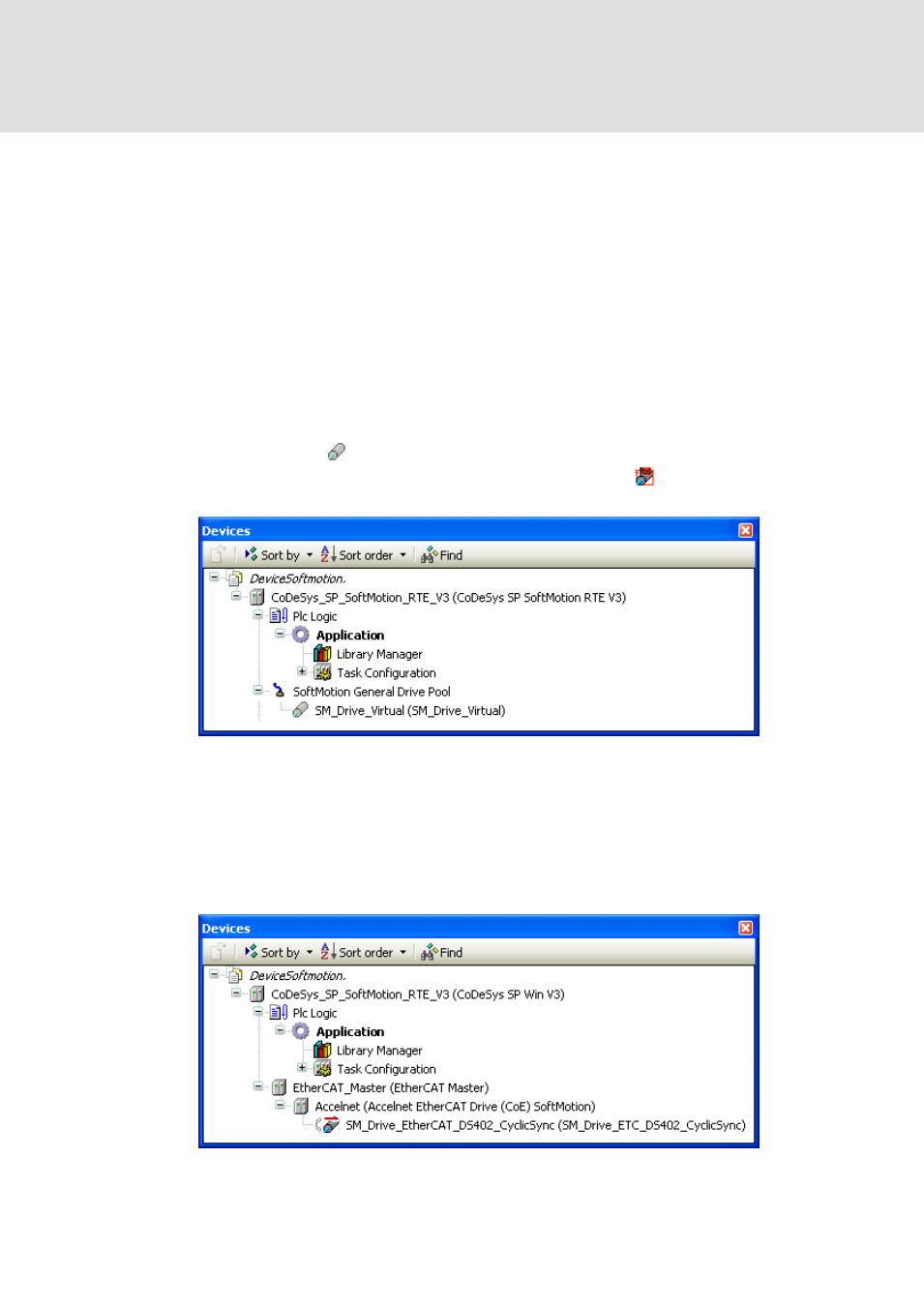
Abb. 511 Exemplary configuration with free drive device
• Configuration as connected drive device
These drive devices stand in a one-to-one correlation with another device
representing the drive within the field bus topology. The icons associated to these
drive devices are augmented by little signs that shall indicate the related field bus
type. Any standard servo drive for example is connected to the controller via a field
bus.
Abb. 512 Exemplary configuration with connected drive device