L-force | plc designer – Lenze PLC Designer PLC Designer (R3-1) User Manual
Page 439
L-force | PLC Designer
Menu Commands sorted by Categories
DMS 4.1 EN 03/2011 TD29
437
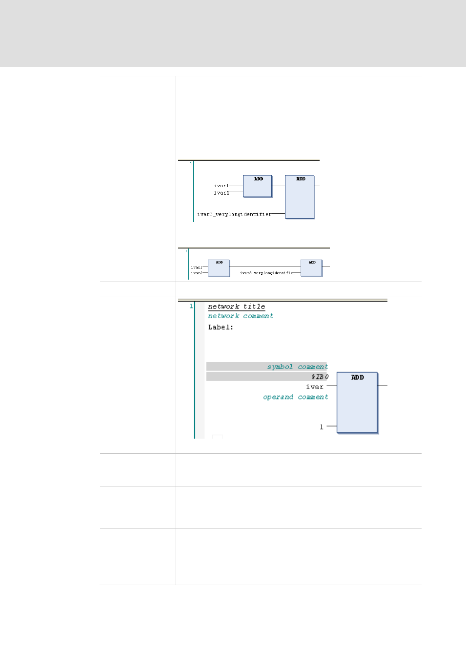
Connect boxes with
straight lines:
If this option is activated, the network components will be arranged in a way
that the lines between are of a fix, short length, thus as far as possible
reducing the horizontal space required for displaying the networks. This might
effect that boxes are enlarged in height, e.g. to provide enough space for input
and output elements. If the option is not activated, the elements will keep their
standard size and the connection lines adapt to the need of space.
Example
Option activated:
Option deactivated:
Show network title
The network title - if defined - is displayed in the upper left corner of a network.
Components in the editor view, example: FUP network
Show network
comment
The network comment - if defined - is displayed in the upper left corner line of
a network. If the network title is visible also, the comment will appear in the
line below the title.
Show operand
comment
The comment which might be assigned to a variable in the implementation
part of the editor will be displayed. The operand comment only refers to the
current place of usage of the variable, in contrast to the "symbol comment",
which is defined at the declaration of a variable.
Show symbol
comment
For each symbol (variable) which has got a comment in its declaration, this
comment will be displayed above the symbol's identifier. Regard that
additionally or instead of also a local "operand comment" can be assigned.
Show symbol address
For each symbol (variable) the assigned address will be displayed above the
symbol's identifier.