L-force | plc designer – Lenze PLC Designer PLC Designer (R3-1) User Manual
Page 876
L-force | PLC Designer
Device Editors
874
DMS 4.1 EN 03/2011 TD29
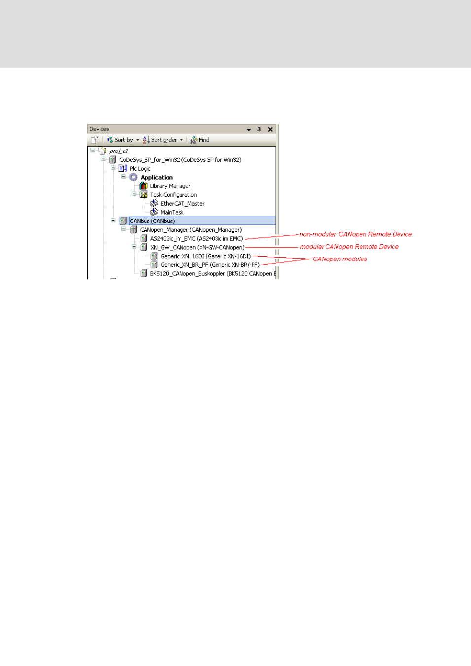
• Below the CANopen Manager finally the particular CANopen devices objects
("slaves") provided with the hardware can be added. Here two types are possible:
non-modular devices and modular devices. Below modular devices further CAN
modules can be inserted and automatic I/O mapping can be used.
Abb. 480 Example: CANbus configuration tree
Configuration
After having mapped the CANbus hardware environment in the devices tree, use the
configuration dialogs to check or adapt the default configuration settings:
For the device entry which is currently selected in the devices tree, the appropriate
configuration dialog will open in the Device Editor window when you perform a
double-click or use command 'Edit object'.
The configuration possibilities for a device or module depend on the definitions read
from the device description file.
Notice the Device Editor Options for general editor settings: For example generic
dialogs might be set invisible.
A CANopen configuration dialog always is entitled with the name of the module and
can provide tabs containing the following sub-dialogs:
For a CANbus:
• CANbus (general settings, currently only: baud rate)
• CANbus Configuration (settings as provided by the *.devdesc-file)
• CANbus I/O Mapping
• Status
• Information