L-force | plc designer – Lenze PLC Designer PLC Designer (R3-1) User Manual
Page 611
L-force | PLC Designer
General Editors
DMS 4.1 EN 03/2011 TD29
609
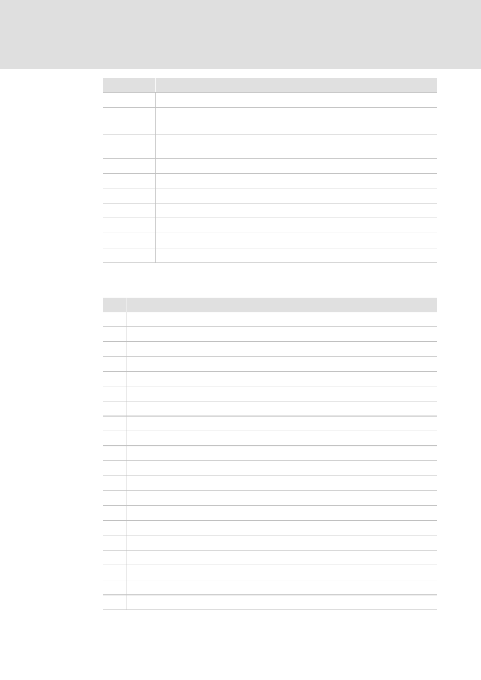
Letter
Function
Q
Target position of the additional linear axis Q
R
Radius (G02/G03) – alternatively to "I","J"
or ratio of the minor to the major elliptical axis (G08/G09) [0..1]
S
Switch on (>0) / off (<0) the S-profile for linear axes
3: Z-axis (2D-mode only), 7: P-axis, 8: Q-axis, 9: U-axis, 10: V-axis, 11: W-axis
T
Command specific parameter.
U
Target position of the additional linear axis U
V
Target position of the additional linear axis V
W
Target position of the additional linear axis W
X
X-coordinate of the target position
Y
Y-coordinate of the target position
Z
Z-coordinate of the target position
Instructions :
Letter Function
G00
Direct movement without tool contact, positioning
G01
Linear (straight) movement with tool contact
G02
Circle(-segment) clockwise
G03
Circle(-segment) counterclockwise
G04
Delay Time
G05
Point of a 2D cardinal spline
G06
Parable
G08
Ellipsis(-segment) clockwise
G09
Ellipsis(-segment) counterclockwise
G10
Point of a 3D cardinal spline
G15
Change to 2D.
G16
Change to 3D by activating the 3D mode with plane normal I/J/K.
G17
Change to 3D by activating the 3D mode in X/Y plane.
G18
Change to 3D by activating the 3D mode in Z/X plane.
G19
Change to 3D by activating the 3D mode in Y/Z plane.
G20
Conditional jump (to L if K<>0)
G36
Write value (D) to variable (O)
G37
Increment variable (O) by value (D)
G40
End of the tool radius correction
G41
Start the tool radius correction to the left of the workpiece