Ladder diagrams – Maple Systems MAPware-7000 User Manual
Page 277
MAPware-7000 Programming Manual
277
1010-1040, Rev. 02
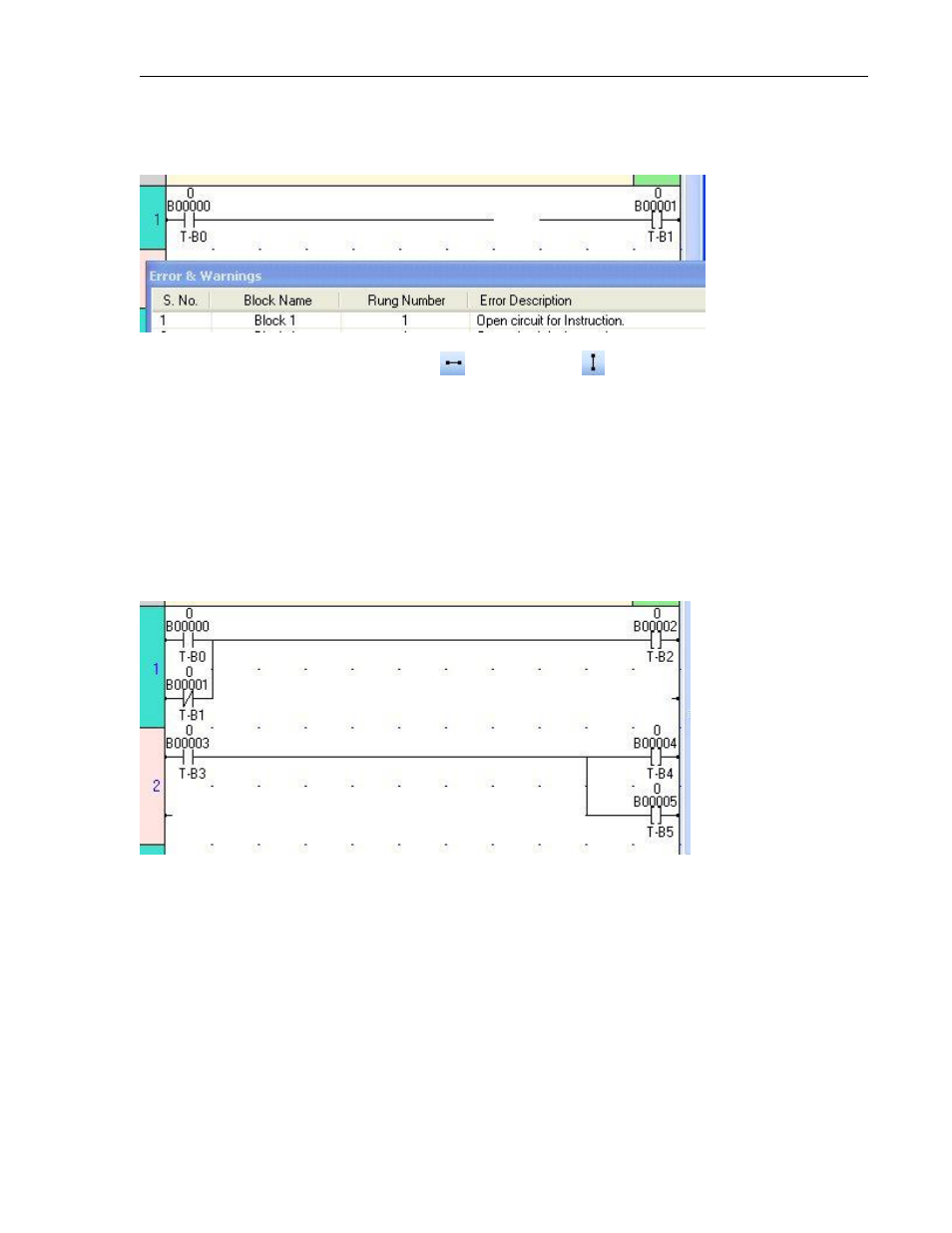
If the elements in a net are not connected, the software will display an error message in the
View Window when you compile your project.
Connect elements using the horizontal link
and vertical link
connectors.
Ladder Diagrams
The MAPware-7000 software uses ‘ladder diagrams’. A ladder diagram is a language-composed
program that uses relay symbols as a base for an image similar to a hard-wired relay sequence.
In order to achieve an efficient data-processing program, ladder diagrams are used.
Ladder diagrams are constructed of units called ‘rungs’. A rung is defined as one network of
interconnected elements (i.e. coils, contacts, instructions) between the left and right power rail.
Each rung can have multiple lines.
Example of two multi-line rungs
Rung numbers are a series of numbers starting from 1, and cannot be skipped. A Logic
Block contains one or more rungs. There is no limit to the number of rungs within a
block. Note: It is limited only by available ladder memory of selected model.
The size of any one rung is limited to 50 lines x 11 columns.
If multiple logic blocks are created, each block is executed in sequence. In each block,
each rung is executed in sequence until the END instruction is reached.