Chapter 11 – (ladder) logic blocks, Introduction, Ladder logic – Maple Systems MAPware-7000 User Manual
Page 276: Ladder nets
276
MAPware-7000 Programming Manual
1010-1040, Rev. 02
Chapter 11 – (Ladder) Logic Blocks
Introduction
Logic blocks are a very useful and significant part of the feature set of the HMC7000 products. A
logic block is a series of ladder logic instructions or commands that is executed by the HMC7000.
As you will see later in this chapter, there are different types of logic blocks. These blocks vary
according to how they are initiated and in the order of execution. The following six types of
logic blocks are supported:
Main program
Power up
Timer Interrupt
I/O Interrupt #1 (HMC7030A-L only)
I/O Interrupt #2 (HMC7030A-L only)
Subroutine
Multiple logic blocks of each type can be created (maximum of 256 per type). There is no limit
to memory for each logic block created except for the overall memory limitation of the HMC.
Ladder Logic
Ladder Logic is a form of programming language used primarily in programmable logic
controllers. It is based upon Boolean principals that attempt to simulate actual construction of
control applications that use mechanical switches and lamps. Ladder diagrams are composed of
different
types of contact, coil and function block elements. These elements are placed in nets.
In any ladder diagram, the contacts represent input conditions. They lead power from the left
rail to the right rail.
Coils represent output instructions. In order for output coils to be activated, the logical state of
the contacts must allow the power to flow through the net to the coil.
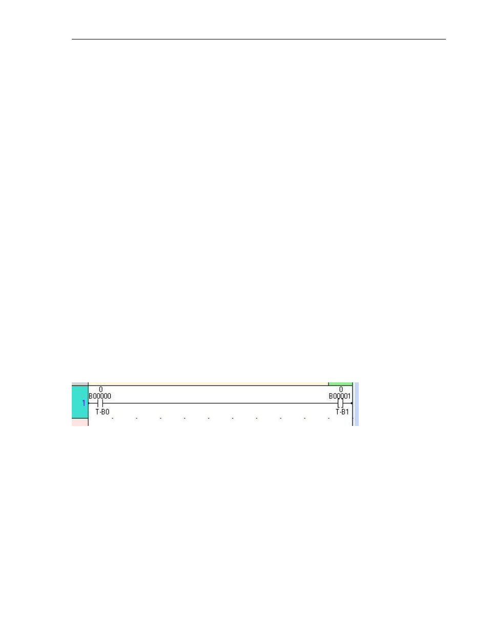
Ladder Nets
The ladder diagram contains a left and right rail. Between these rails, the control application is
arranged in nets. A net contains a row of ladder elements that drive a coil. Power flows through
the ladder elements in a net from left to right. Each net must contain only one rung. This is why
the first ladder element in the net must touch the left ladder rail. All of the elements in a net
must be connected to allow power flow. You must connect the last element on the right to the
right side of the ladder in each net.