1 prepare controller for commissioning, Prepare controller for commissioning, 3commissioning – Lenze 8400 motec User Manual
Page 35
Lenze · 8400 motec · Reference manual · DMS 4.1 EN · 08/2013 · TD05
35
3
Commissioning
3.5
Commissioning of the "Actuating drive speed" technology application
_ _ _ _ _ _ _ _ _ _ _ _ _ _ _ _ _ _ _ _ _ _ _ _ _ _ _ _ _ _ _ _ _ _ _ _ _ _ _ _ _ _ _ _ _ _ _ _ _ _ _ _ _ _ _ _ _ _ _ _ _ _ _ _
3.5.1
Prepare controller for commissioning
1. Wiring the power and control terminals
• Use the mounting instructions supplied with the controller in order to connect the power and
control terminals correctly.
• Assign the digital inputs so that your application can be displayed by one of the
preconfigured control modes (
) for terminal control:
2. Drive Unit: Check switches DIP1 and DIP2.
• DIP1/switch 1 must be set to "OFF" in order that no parameters of the memory module are
overwritten when the device is started.
• See display parameters
and
for details.
3. Communication Unit CANopen or PROFIBUS: Set DIP3 switch.
• See display parameters C00349 (CANopen) or C13920 (PROFIBUS) for details.
4. Position the drive unit carefully onto the communication unit and fix it using the four screws.
5. Inhibit controller: Set RFR terminal to LOW level or open the contact.
6. Switch on voltage supply of the controller.
• Information on some operating states can be quickly obtained via the two-colored LED
display on the top of the device.
7. Establish a connection to the controller, e.g. via USB diagnostic adapter:
• Remove the cover of the diagnostic interface on the top of the device and connect the USB
diagnostic adapter to the diagnostic interface.
• establish a connection between the USB diagnostic adapter and the PC via a free USB port.
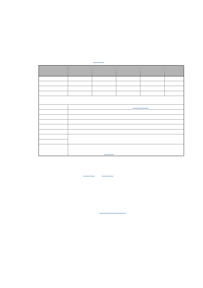
Assignment of the digital terminals
Control mode
DI1
DI2
DI3
DI4
DI5
Terminals 0
JOG 1/3
JOG 2/3
DCB
Cw/Ccw
BrkRelease
Terminals 2
JOG 1/3
JOG 2/3
QSP
Cw/Ccw
BrkRelease
Terminals 11
Cw/Ccw
DCB
MPotUp
MPotDown
BrkRelease
Terminal 16
JOG 1/3
JOG 2/3
Cw/QSP
Ccw/QSP
BrkRelease
Abbreviations used:
JOG Selection of fixed setpoints 1 ... 3 parameterised in
DCB Manual DC-injection braking
Cw/Ccw CW/CCW rotation
QSP Quick stop
MPotUp Motor potentiometer: Increase speed
MPotDown Motor potentiometer: Reduce speed
Cw/QSP Fail-safe selection of the direction of rotation in connection with quick stop
Ccw/QSP
BrkRelease Release holding brake manually
• In the Lenze setting, the brake control is switched off (not active).
Set operating mode in