9diagnostics & error management – Lenze 8400 motec User Manual
Page 295
Lenze · 8400 motec · Reference manual · DMS 4.1 EN · 08/2013 · TD05
295
9
Diagnostics & error management
9.7
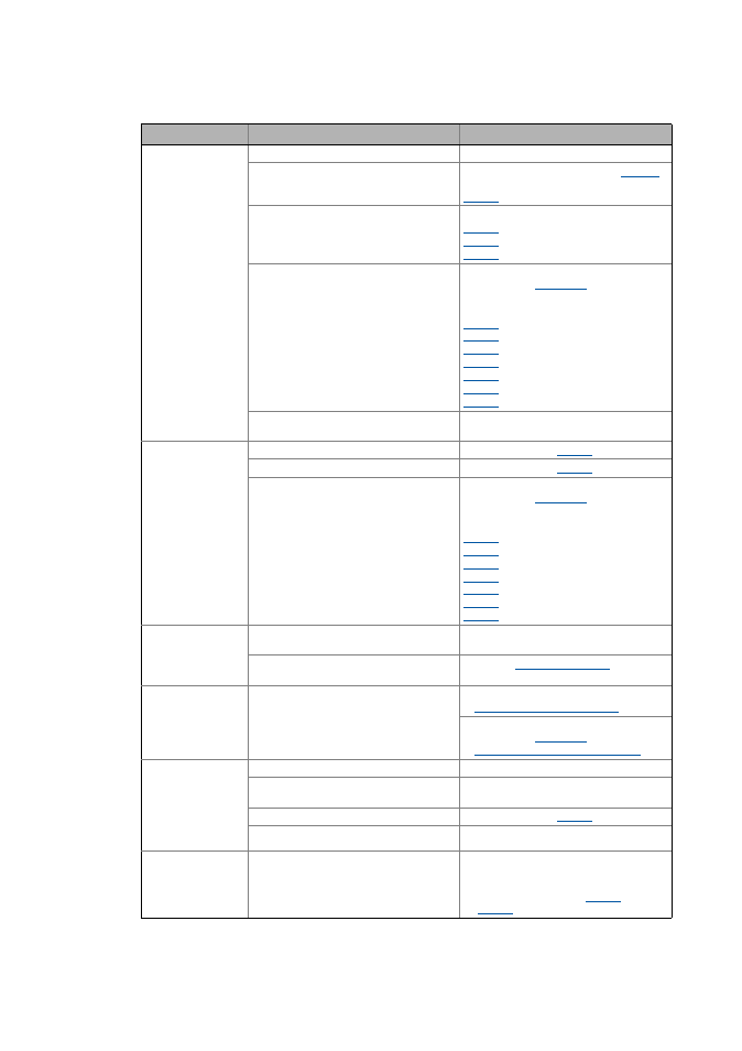
Maloperation of the drive
_ _ _ _ _ _ _ _ _ _ _ _ _ _ _ _ _ _ _ _ _ _ _ _ _ _ _ _ _ _ _ _ _ _ _ _ _ _ _ _ _ _ _ _ _ _ _ _ _ _ _ _ _ _ _ _ _ _ _ _ _ _ _ _
Motor rotates irregu-
larly
Motor cable is defective
Check motor cable
Maximum motor current in motor or genera-
tor mode is set too low
Adjust settings to the application:
Imax in motor mode
: Imax in generator mode
Motor is underexcited or overexcited
Check parameterisation:
: Motor control
: VFC: V/f base frequency
: VFC: Vmin boost
Rated motor data (stator resistance, speed,
current, frequency, voltage) and cos ϕ and/
or magnetising inductance is not adapted to
the motor data
Execute automatic motor parameter identifi-
cation with the
device command
- or -
Adjust motor parameters manually:
: Motor stator resistance
: Rated motor speed
: Rated motor current
: Rated motor frequency
: Rated motor voltage
: Motor cosine phi
: Motor magnetising inductance
Motor windings are wired incorrectly
Reverse from star connection to delta con-
nection
Motor consumes too
much current
V
min
boost has been selected too high
V/f base frequency has been selected too low Correct setting with
Rated motor data (stator resistance, speed,
current, frequency, voltage) and cos ϕ and/
or magnetising inductance is not adapted to
the motor data
Execute automatic motor parameter identifi-
cation with the
device command
- or -
Adjust motor parameters manually:
: Motor stator resistance
: Rated motor speed
: Rated motor current
: Rated motor frequency
: Rated motor voltage
: Motor cosine phi
: Motor magnetising inductance
Motor parameter
identification is
aborted with error
LP1
Motor is too small compared to the rated de-
vice power (>1 : 3)
Use device with lower rated power
DC-injection braking (DCB) is active via ter-
minal
Deactivate
Drive behaviour with
vector control is not
satisfactory
different
Optimise or manually adapt vector control
Sensorless vector control (SLVC)
Execute automatic motor parameter identifi-
cation with the
device command
Automatic motor data identification
Torque dip in field
weakening range
or
motor stalling when
being operated in the
field weakening
range
Motor is overloaded
Check motor load
Motor windings are wired incorrectly
Reverse from star connection to delta con-
nection
V/f base frequency is set too high
Correct setting with
Mains voltage too low
Increase mains voltage
Parameter changes
are not accepted
Settings according to DIP1, DIP2, P1, P2 and
P3 are active (local mode)
Set DIP1/switch 1 to "OFF" in order that no
parameters of the memory module are over-
written when the device is started.
• See display parameters
and
for details.
Maloperation
Cause
Remedy