1about this documentation – Lenze 8400 motec User Manual
Page 13
Lenze · 8400 motec · Reference manual · DMS 4.1 EN · 08/2013 · TD05
13
1
About this documentation
1.3
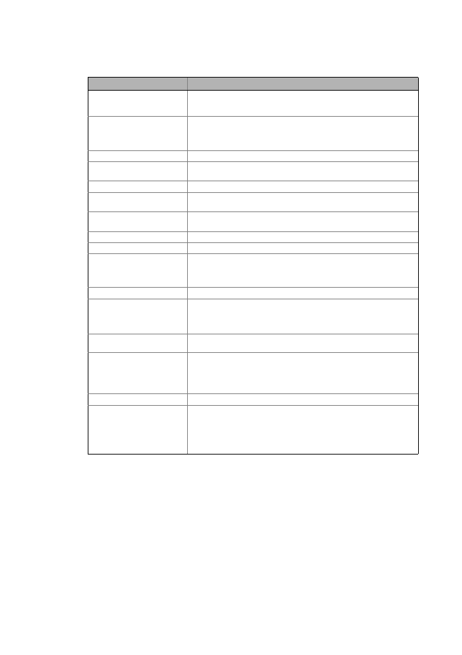
Terminology used
_ _ _ _ _ _ _ _ _ _ _ _ _ _ _ _ _ _ _ _ _ _ _ _ _ _ _ _ _ _ _ _ _ _ _ _ _ _ _ _ _ _ _ _ _ _ _ _ _ _ _ _ _ _ _ _ _ _ _ _ _ _ _ _
EPM
Memory module on which all parametes of the drive system are saved non-vol-
atilely. These include the parameters of the controller and communication-rele-
vant parameters for the communication unit used.
Function block
A function block can be compared with an integrated circuit that contains a cer-
tain control logic and delivers one or several values when being executed.
• Each function block has a unique identifier, e.g. "L_MPot_1" (motor potenti-
ometer function)
Holding brake
The holding brake serves to hold the rotor by means of a mechanical unit.
LA
Abbreviation: Lenze Application block
• Example: "LA_NCtrl" – block for the "actuating drive speed" application.
Lenze setting
This setting is the default factory setting of the device.
LP
Abbreviation: Lenze Port block
• Example: "LP_Network_In" – port block for fieldbus communication.
LS
Abbreviation: Lenze System block
• Example: "LS_DigitalInput" – system block for digital input signals.
Port block
Block for implementing the process data transfer via a fieldbus
QSP
Quick stop
Service brake
The service brake serves to shutdown rotary or translatory masses in motion in
a controlled manner. The energy to be dissipated in this process is converted into
heat in the form of friction energy. This process is a regular and recurring oper-
ating mode.
SLVC
Motor control: Sensorless vector control ("SensorLess Vector Control")
Subcode
If a code contains several parameters, these are stored in "subcodes".
This Manual uses a slash "/" as a separator between code and subcode
(e.g. "C00039/1").
The term is usually called "subindex".
System block
In the application, system blocks provide interfaces to basic functions and to the
hardware of the controller (e.g. to the digital inputs).
USB diagnostic adapter
The USB diagnostic adapter is used for the operation, parameterisation, and di-
agnostics of the controller. Data are exchanged between the PC (USB connec-
tion) and the controller (diagnostic interface on the front) via the diagnostic
adapter.
• Order designation: E94AZCUS
VFCplus
Motor control: V/f characteristic control ("Voltage Frequency Control")
VFCplusEco
Motor control: V/f characteristic control - energy-saving
In this motor control mode, the controller adapts the motor voltage to the re-
quirements of the load. Especially at speeds lower than 50 % of the rated speed
and a reduced torque, losses in the motor and in the controller can be reduced.
Hence, the usually bad efficiency of the drive in partial load operational range is
increased significantly.
Term
Meaning