1 optimise current controller, 2 optimise speed controller, Optimise current controller – Lenze 8400 motec User Manual
Page 135: Optimise speed controller, 5motor control (mctrl)
Lenze · 8400 motec · Reference manual · DMS 4.1 EN · 08/2013 · TD05
135
5
Motor control (MCTRL)
5.9
Sensorless control for synchronous motors (SLPSM)
_ _ _ _ _ _ _ _ _ _ _ _ _ _ _ _ _ _ _ _ _ _ _ _ _ _ _ _ _ _ _ _ _ _ _ _ _ _ _ _ _ _ _ _ _ _ _ _ _ _ _ _ _ _ _ _ _ _ _ _ _ _ _ _
5.9.4.1
Optimise current controller
An optimisation of the current controller is sensible since the two control parameters gain (
and reset time (
) depend on the required maximum current and the set switching
frequency.
• Gain and reset time can be calculated as per the following formulae:
5.9.4.2
Optimise speed controller
The speed controller is designed as a PID controller. For optimum behaviour, the PID speed controller
has to be optimised and the overall mass inertia of the drive train has to be determined.
• In the Lenze setting, the configuration of the speed controller provides robustness and
moderate dynamics.
Note!
An optimisation of the current controller should generally be carried out unless a power-
adapted standard motor is used or the motor has been selected from the motor
catalogue of the »Engineer«!
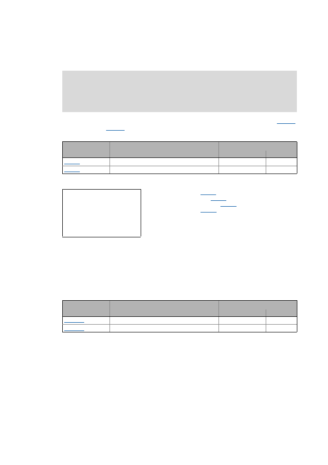
Parameter
Info
Lenze setting
Value Unit
Vp current controller
7.00 V/A
Ti current controller
10.61 ms
V
p
= Current controller gain (
)
T
i
= Current controller reset time (
)
L
ss
= Motor stator leakage inductance (
R
s
= Motor stator resistance (
T
E
= Equivalent time constant (= 500 μs)
V
p
L
ss
H
[ ]
T
E
s
[ ]
----------------
=
T
i
L
ss
H
[ ]
R
s
Ω
[ ]
----------------
=
Parameter
Info
Lenze setting
Value Unit
SLPSM: Vp speed controller
3.00
SLPSM: Ti speed controller
100.0 ms