3 interface description, 1 wdrivecontrol control word, Interface description – Lenze 8400 motec User Manual
Page 244: Wdrivecontrol control word, 7technology applications
7
Technology applications
7.4
TA "Switch-off positioning"
244
Lenze · 8400 motec · Reference manual · DMS 4.1 EN · 08/2013 · TD05
_ _ _ _ _ _ _ _ _ _ _ _ _ _ _ _ _ _ _ _ _ _ _ _ _ _ _ _ _ _ _ _ _ _ _ _ _ _ _ _ _ _ _ _ _ _ _ _ _ _ _ _ _ _ _ _ _ _ _ _ _ _ _ _
7.4.3
Interface description
7.4.3.1
wDriveControl control word
In the control mode "40: Network (MCI/CAN)", the controller is controlled by a master control (e.g.
IPC) via the wDriveControl control word.
• The process data word received from the master control is provided to the application via the
at the wDriveControl input.
• Display parameter:
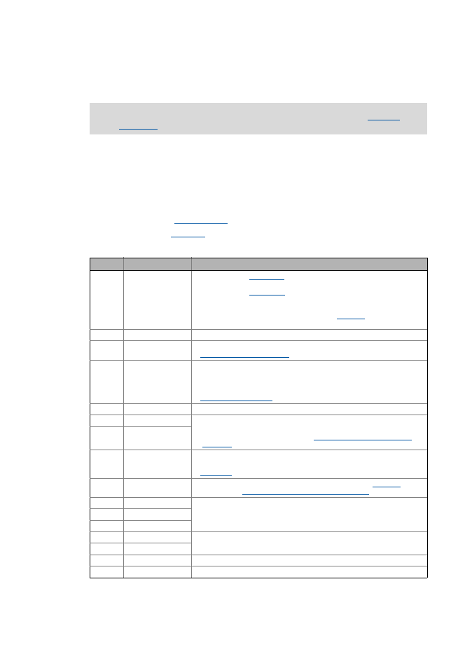
• The bit assignment of the control word can be obtained from the following table:
All input and output interfaces are described in the subchapter entitled "
description
" of the "speed actuating drive" application.
Bit
Name
Function
Bit 0 SwitchOn
1 ≡ Change to the "
" device status
• This bit must be set in the CAN/MCI control word to ensure that the device
changes to the "
" device status after mains connection without
the need for a master control specifying this bit via fieldbus.
• If control via a bus system is not wanted (e.g. in the case of control via
terminals), the wDriveCtrl output signal of the
system block can be
connected to the control word inputs.
Bit 1 DisableVoltage
1 ≡ Inhibit inverter control (pulse inhibit)
Bit 2 SetQuickStop
1 ≡ Activate quick stop (QSP).
Activate/deactivate quick stop ( 65)
Bit 3 EnableOperation
1 ≡ Enable controller (RFR)
• If control via terminals is performed, this bit must be set both in the CAN
control word and in the MCI control word. Otherwise, the controller is
inhibited.
Enable/Inhibit controller ( 65)
Bit 4 ModeSpecific_1
Reserved (currently not assigned)
Bit 5 InputSel1
Binary coded selection of the switch-off position 1 ... 3
• Activation of the signal pairs bSlowDown1/bStop1, bSlowDown2/bStop2 or
bSlowDown3/bStop3 according to the
Truth table for activating the pre-
switch off
.
Bit 6 InputSel2
Bit 7 ResetFault
1 ≡ Reset fault (trip reset)
• Acknowledge error message (if the error cause has been eliminated).
Bit 8 Rfg0
Ramping down the setpoint generator in the downstream FB
according to the
Truth table for activating the pre-switch off
Bit 9 reserved_1
Reserved (currently not assigned)
Bit 10 reserved_2
Bit 11 LenzeSpecific_1
Bit 12 JogSpeed1
Binary coded selection of the fixed setpoints (JOG setpoints)
Bit 13 JogSpeed2
Bit 14 SetFail
1 ≡ Set error (trip set)
Bit 15 LenzeSpecific_4
Reserved (currently not assigned)