Installing the replacement power supply, Power supply (blade element), Attributes – HP Integrity NonStop J-Series User Manual
Page 190: Power supply, Power supplies, Blade element power supply
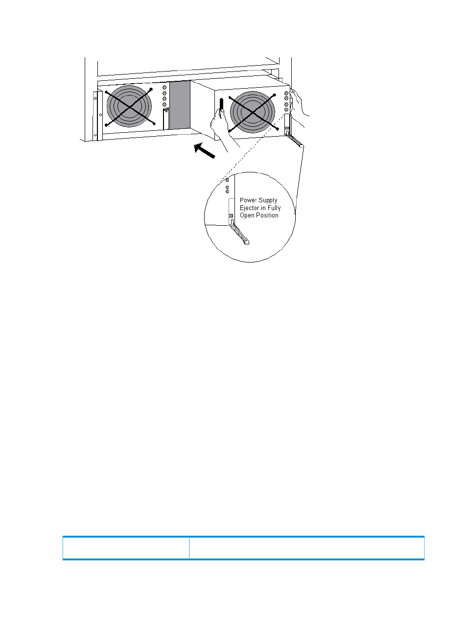
Installing the Replacement Power Supply
1.
Lower the ejector on the replacement power supply to its fully open position.
2.
With one hand, grasp the handle of the power supply. Use your other hand to support the
weight of the power supply. Then slowly push the power supply all the way into the empty
slot.
3.
Raise the ejector on the replacement power supply to its fully closed position. This action
connects the power supply to the power interface board (PIB) and the AC power cord directly
behind it.
The green power-on LED above the replacement power supply should now be lit. If the LED is
not lit, either reseat the power supply or install a different power supply.
4.
Replace the front panel on the power shelf.
5.
Return to the OSM Service Connection Actions dialog box and click Continue to indicate that
you have completed the physical CRU replacement. OSM then verifies the status of the new
power supply. If it is found to be functional, OSM enables the associated battery that was
disabled earlier in the procedure.
Power Supply (Blade Element)
Subcomponent of a
. There are two power supplies in each enclosure.
Location in OSM Tree: System > Group > Blade Complex > Blade Element > Blade Element Power
Supply
Example: Blade Element Power Supply (400.1.3)
Attributes
Power Supply
Displayed in the Attributes tab and Attributes dialog box only if the value is
something other than OK.
Service State
190 System Resources