Using forces – Rockwell Automation 9323-S5500D A.I. SERIES MICROLOGIX 1000 AND PLC-500 SOFTW User Manual
Page 451
MicroLogix 1000 and PLC-500 A.I. Series Software Reference
19-20
When viewing a project running under PLC-500 A.I., the displayed state of inputs and
outputs on the ladder display reflects the data table values, not the actual state of the
device. Input forces affect the data table, and thus will affect the program while it is
running. Output forces occur
after
a rung has been executed, and affect only the actual
outputs, not the data table. The output state shown on the screen may not match the
state of the actual output device.
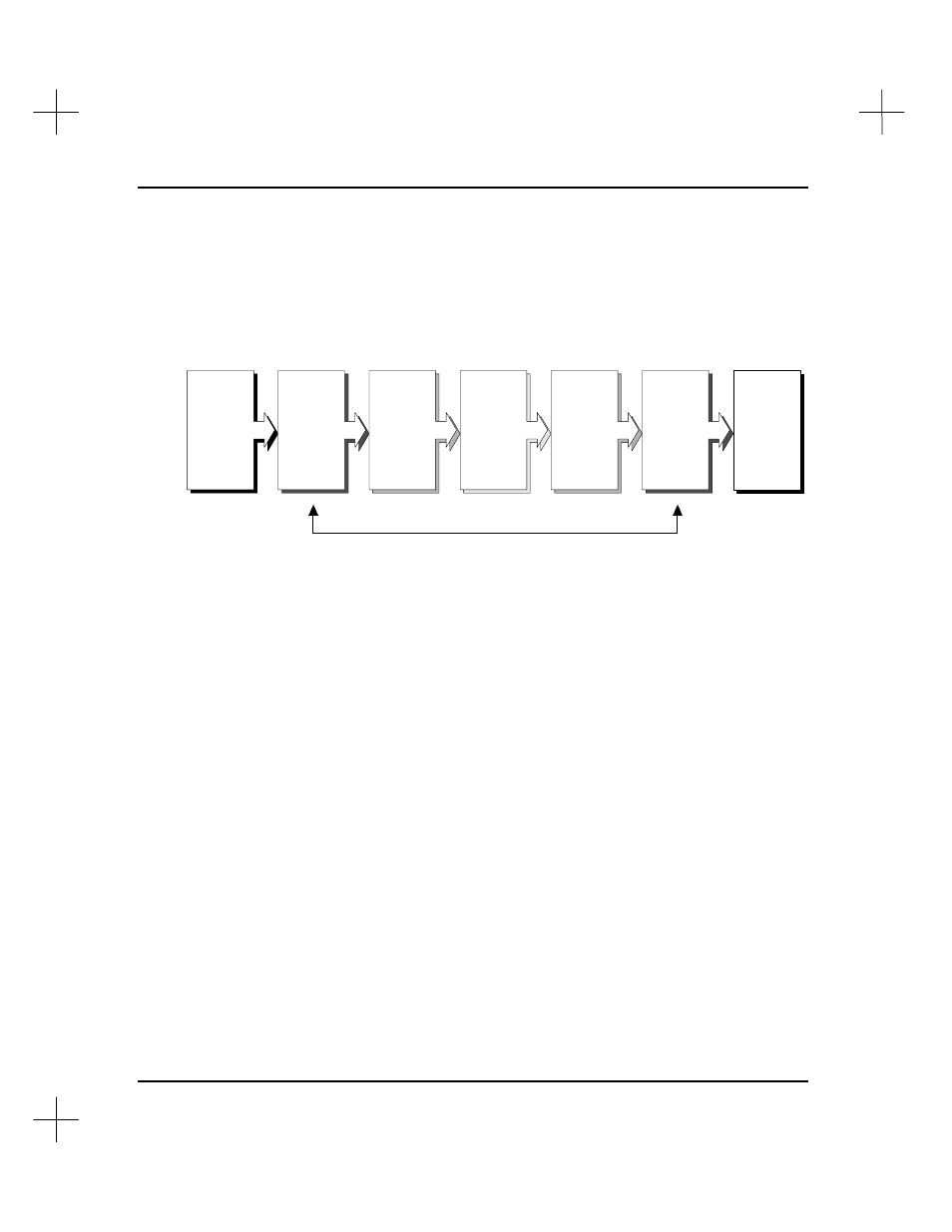
The force table functions like a filter or mask.
State of
Actual
Output
Device
Ladder
Program
Execution
State of
Actual
Input
Device
Force
Table
(Inputs)
Force
Table
(Outputs)
Data
Table
(Inputs)
Data
Table
(Outputs)
Notice that the input data table is updated before the ladder program executes and the
output data table is updated after the ladder program executes.
Using Forces
Whenever you force a contact, the word ON or OFF appears on the ladder display, just
below the instructions referencing the forced address. Remember that the ladder
program, and the reverse video used to indicate contact status, refer to the data table,
not the force table. This means that forced outputs will not be highlighted in the ladder
display unless the logic controlling the output is true.