A one-rung ladder program – Rockwell Automation 9323-S5500D A.I. SERIES MICROLOGIX 1000 AND PLC-500 SOFTW User Manual
Page 108
Ladder Program Basics
5-3
A One-Rung Ladder Program
A ladder program consists of individual rungs, each consisting of at least one output
instruction. A rung may have at most 128 instructions: a combination of 0 to 127
input instructions and 1 to 75 output instructions. Various rung constructions are
discussed later. Every program file must have an END rung. This is automatically
programmed by PLC-500 A.I.
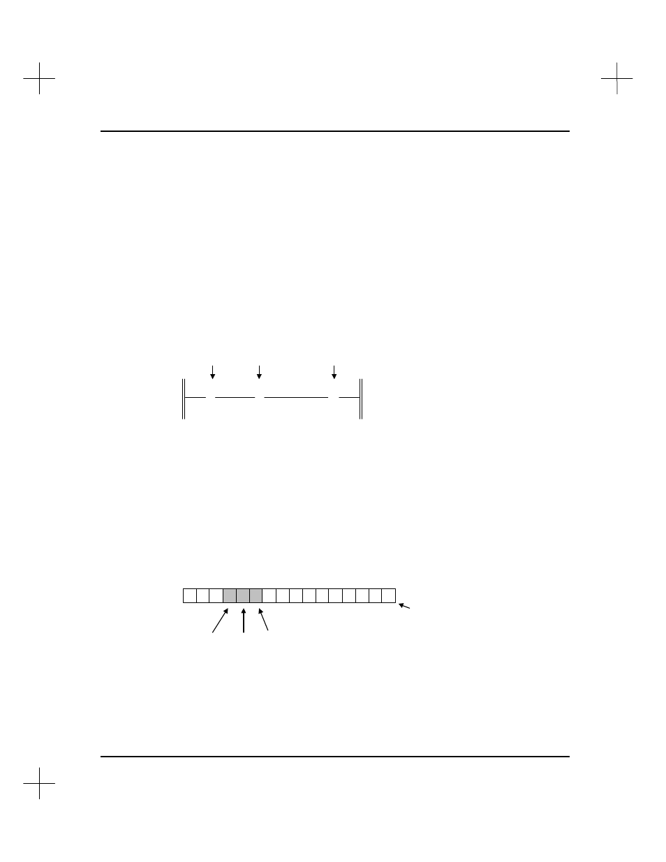
The ladder rung below has two input instructions and an output instruction. An output
instruction always appears at the right, next to the right power rail. Input instructions
always appear to the left of the output instruction.
] [
] [
/
( )
B3
B3
B3
10
11
12
XIC
XIO
OTE
Input Instructions
Output Instruction
XIC
=Examine if Closed
Address
B3/10
XIO
=Examine if Open
Address
B3/11
OTE
=Output Energize
Address
B3/12
A simple rung, using relay logic instructions
Note that each instruction in the diagram above has an address. This address identifies
a storage location in the processor’s data files, where the on/off state of the instruction
is stored. For more information on addressing, refer to
Appendix C - Data File
Organization and Addressing
in the
Instruction Set Reference
. Addresses of the above
instructions indicate Bit data file 3 (B3), bits 10, 11, and 12:
15 14 13 12 11 10 9
8
7
6
5
4
3
2
1
0
0
0
1
0
0
1
0
0
0
0 0
0
0
0
0
0
Bit Data File 3,
Element 0
XIO
XIC
OTE
In the preceding diagram, we indicated that bit 10 is logic 1 (on), bit 11 is logic 0 (off),
and bit 12 is logic 1 (on). These logic states indicate whether an instruction is true or
false, as pointed out in the table below.