A four-rung ladder program – Rockwell Automation 9323-S5500D A.I. SERIES MICROLOGIX 1000 AND PLC-500 SOFTW User Manual
Page 115
MicroLogix 1000 and PLC-500 A.I. Series Software Reference
5-10
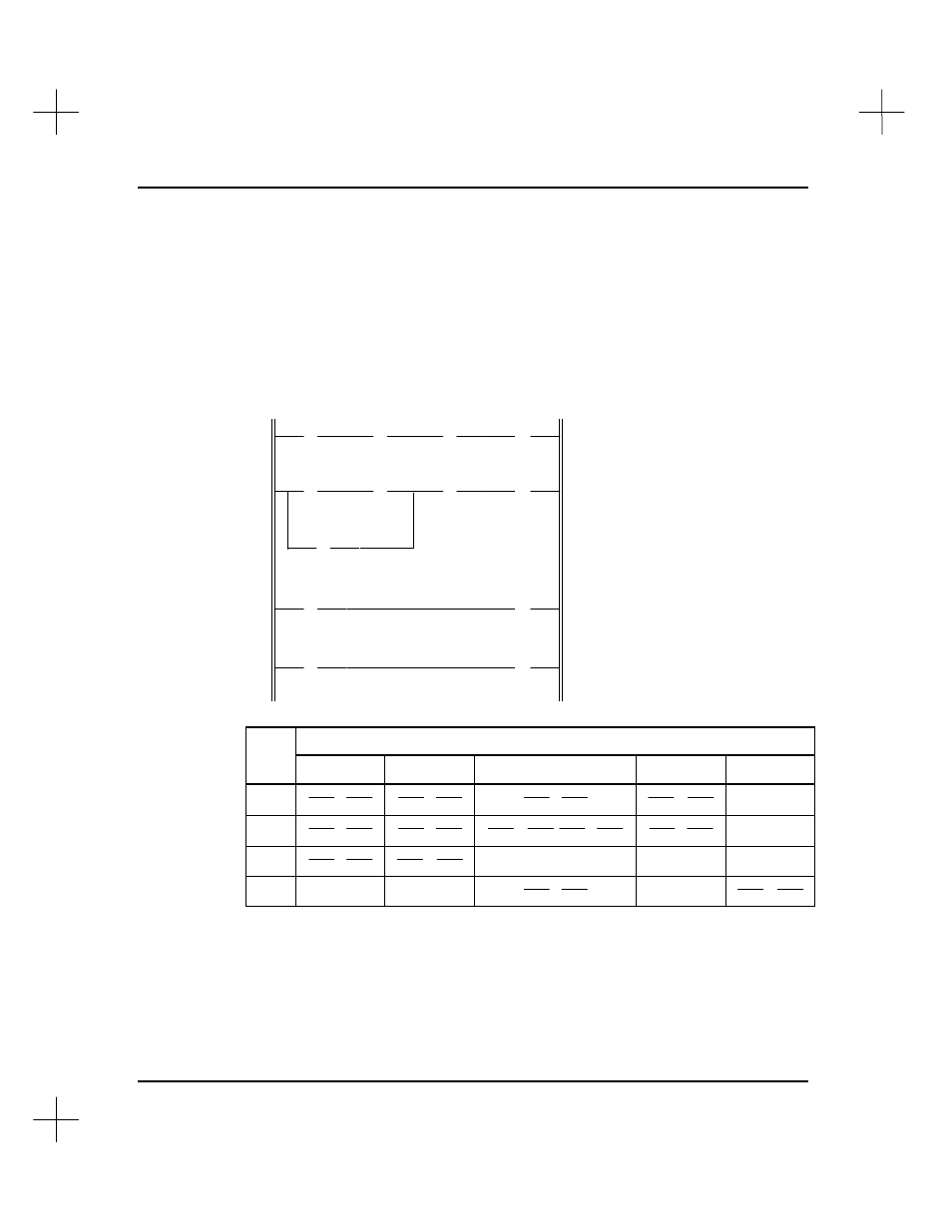
A Four-Rung Ladder Program
The following four-rung ladder program uses the same 3 bit locations as our simple one
rung diagram. It also uses an external input bit address and an external output bit
address. Note that individual bits are addressed repeatedly. For example, B3/11 is
addressed with an XIC instruction in rungs 1 and 4, and it is addressed with both an
XIC and an OTE instruction in rung 2.
] [
] [
/
] [
( )
] [
] [
/
] [
/
( )
] [
] [
] [
( )
( )
I:0
B3
B3
B3
1
10
11
12
I:0
B3
B3
B3
B3
I:0
B3
B3
O:0
1
10
12
11
11
1
10
11
2
1
2
3
4
Bit
Rung
I:0/1
B3/10
B3/11
B3/12
O:0/2
1
] [
] [
/
] [
( )
N/A
2
] [
] [
/
( )
] [
] [
/
N/A
3
] [
( )
N/A
N/A
N/A
4
N/A
N/A
] [
N/A
( )
During normal controller operation, the processor checks the state of the input data file
bits then executes the program instructions individually, rung by rung, from the
beginning to the end of the program. As it executes the instructions, it updates the data
file bits and energizes the appropriate output data file bits accordingly.