Ladder programming – Rockwell Automation 9323-S5500D A.I. SERIES MICROLOGIX 1000 AND PLC-500 SOFTW User Manual
Page 107
MicroLogix 1000 and PLC-500 A.I. Series Software Reference
5-2
Ladder Programming
The ladder program you enter into the controller’s memory will contain bit (relay logic)
instructions representing external input and output devices. It will also contain other
instructions, as described in the
Instruction Set Reference
.
As your program is scanned during controller operation, the changing on/off status of
the external inputs will be applied to your program, energizing and de-energizing
external outputs according to the particular instructions you’ve used.
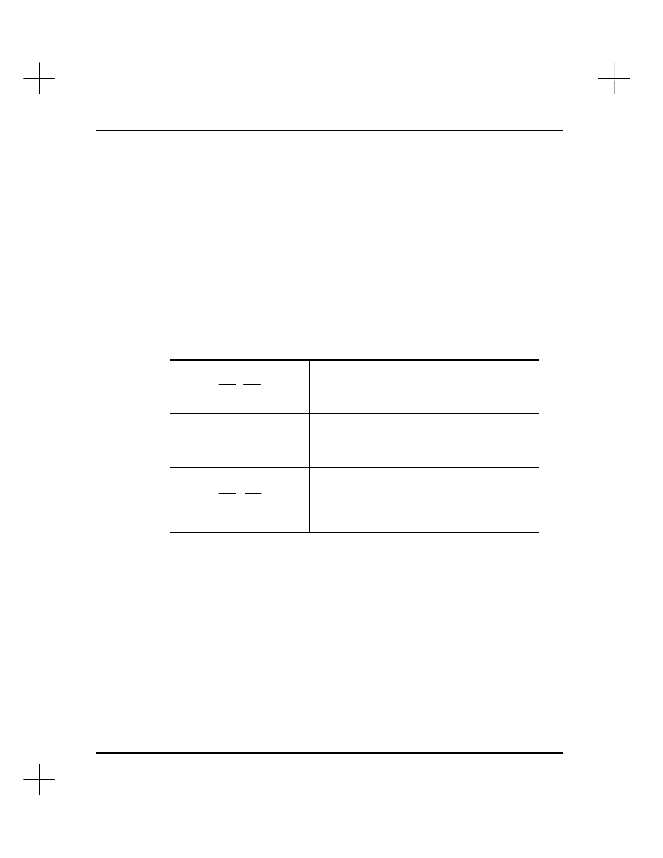
To illustrate how ladder programming works, we chose to use bit (relay logic)
instructions, since they are probably the easiest to understand. The three instructions
we will be discussing in this section are:
Examine if Closed (XIC)
] [
Analogous to the normally open relay contact.
For this instruction, we ask the processor to
“Examine if (the contact is) Closed.”
Examine if Open (XIO)
] [
/
Analogous to the normally closed relay contact.
For this instruction, we ask the processor to
“Examine if (the contact is) Open.”
Output Energize (OTE)
( )
Analogous to the relay coil. The processor
makes this instruction true (analogous to
energizing a coil) when there is a path of true XIC
and XIO instructions in the rung.
Keep in mind that operation of these instructions is similar but not equivalent to that of
relay contacts and coils. In fact, a knowledge of relay control techniques is not a
prerequisite for programming the SLC 500 Programmable Controller.