Rockwell Automation 9323-S5500D A.I. SERIES MICROLOGIX 1000 AND PLC-500 SOFTW User Manual
Page 117
MicroLogix 1000 and PLC-500 A.I. Series Software Reference
5-12
XIC
I:0/1
Instruction Execution
T = true at time of execution
F = false at time of execution
Goes
True
T
F
T
F
T
T
T
F
T
T
T
T
T
Scan 1000
T
F
T
T
T
T
F
T
F
T
T
T
T
Scan 1001
Goes
False
F
F
F
T
F
T
F
T
F
T
T
F
T
Scan 2000
F
F
F
T
F
T
T
T
T
T
T
F
T
Scan 2001
Goes
True
T
T
T
T
T
F
T
T
T
F
F
T
F
Scan 3000
T
F
T
F
T
F
F
F
F
T
F
T
F
Scan 3001
Goes
False
F
F
F
F
F
F
F
F
F
T
F
F
F
Scan 4000
F
F
F
F
F
F
T
F
T
T
F
F
F
Scan 4001
F
F
F
F
F
F
T
F
T
T
F
F
F
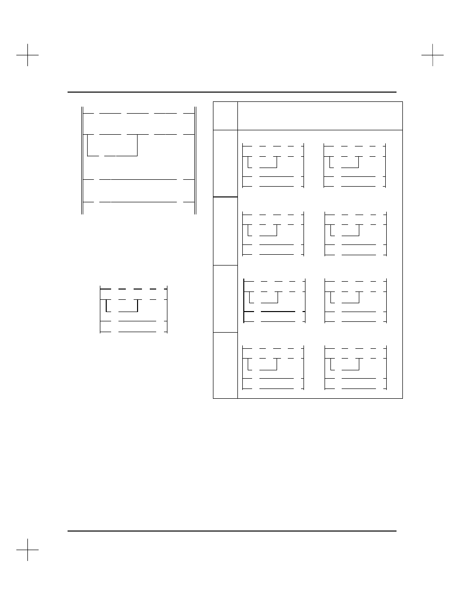
The diagram above is the same one
that appears in the beginning of this
topic. This diagram is also
represented below with each
instruction replaced with a T or F,
indicating the initial True/False status
of the instruction.
The table at the right indicates how the
instructions are executed when XIC
instruction I:0/1 changes state. (I:0/1
represents an external momentary
contact push button.)
] [
] [
/
] [
( )
] [
] [
/
] [
/
( )
] [
] [
] [
( )
( )
I:0
B3
B3
B3
1
10
11
12
I:0
B3
B3
B3
B3
I:0
B3
B3
O:0
1
10
12
11
11
1
10
11
2
1
2
3
4