Rockwell Automation 9323-S5500D A.I. SERIES MICROLOGIX 1000 AND PLC-500 SOFTW User Manual
Page 119
MicroLogix 1000 and PLC-500 A.I. Series Software Reference
5-14
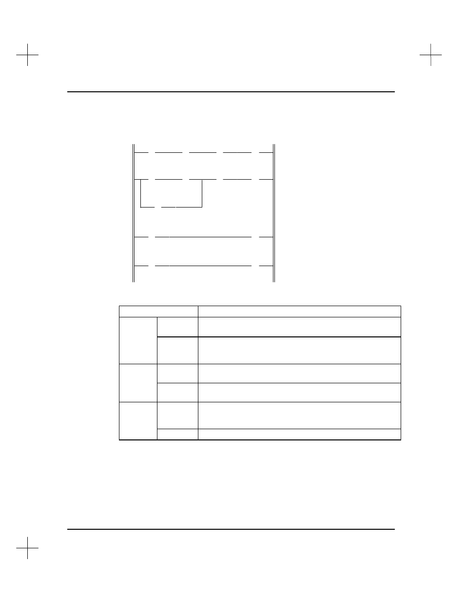
The table below indicates how the operating cycle works for the four rung ladder
program discussed on pages 5-10 through 5-12. Details of program scans 999-1001 are
shown.
] [
] [
/
] [
( )
] [
] [
/
] [
/
( )
] [
] [
] [
( )
( )
I:0
B3
B3
B3
1
10
11
12
I:0
B3
B3
B3
B3
I:0
B3
B3
O:0
1
10
12
11
11
1
10
11
2
1
2
3
4
Scan
Event
Scan
Program
Initial conditions. No changes.
I:0/1 goes true, but has no
effect on the program until after the I/O scan.
999
I/O
Processor determines that external input terminal I:0/1 is On.
Bit I:0/1 in the input data file is changed from 0 to 1. Output
O:0/2 is unchanged.
Scan
1000
Program
Program is scanned. Data files are updated, as affected by bit
I:0/1. Output bit O:0/2 is changed from 0 to 1.
I/O
Output terminal O:0/2 is turned On. Input terminal I:0/1 is
unchanged.
Scan
1001
Program
Program is scanned. Bit changes that took place in the later
part of program scan 1000 are now applied to the first part of
the program.
I/O
No changes.