Figure 17.2 typical emergency stop circuit – Rockwell Automation 8520 9/Series CNC Integration Maintenance Manual Documentation Set User Manual
Page 878
Section 17
Installing 9/Series for CE Compliance
17-6
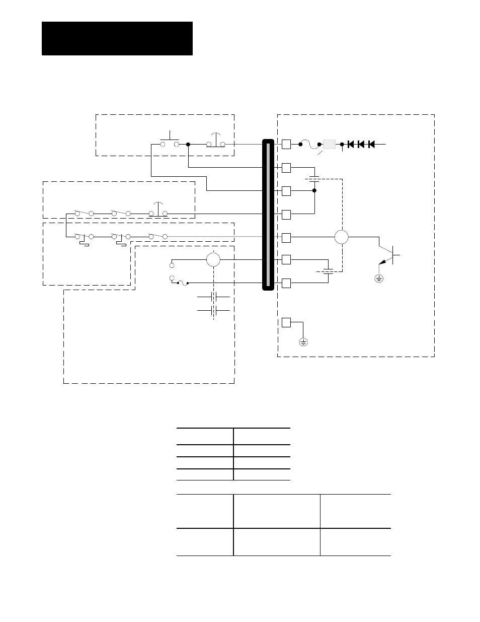
Figure 17.2
Typical Emergency Stop Circuit
MTB PANEL
Motherboard/Processor Board
MACHINE
DRIVES ENCLOSURE
SYSTEM INSTALLER OPTIONS
Motor thermal switches
may be connected
directly
Extreme overtravel
switches
Reset
button
E-STOP
button
Contactors for E-STOP status controlled
devices (servo amp contactor, indicators,
brakes, coolant pumps, etc.)
Drive System Ready
Remote
E-STOP
button
15 V dc
from main
power supply
Reduced
to 12 V dc
filter
250mA
E-STOP relay K
1
12 V dc coil
Contact ratings:
30 V dc
1.4 A
Software
controlled
E-STOP
circuit
K
1B
K
1A
1
2
3
4
5
6
7
common
Customer-supplied
dc power
CR
CR
+
--
customer supplied
fuse (size to protect K1b
contact and your E-Stop
status relay)
E-STOP status
relay
8
Important:
If your control has terminal 8,
then connect it to chassis ground. If
terminal 8 is not present on your control,
then this type of grounding is not necessary.
Ferrite Suppressor Core
Ferrite suppression cores can be aquired through several vendors, including
Dexter Magnetic Materials Division (DMMD):
Country
Phone
Germany
089-857-3071
United Kingdom
0753-680011
United States
1-800-345-4082
Ferrite
Suppression
Core
Specification
Manufacturer
Part Number
250W @ 100 MHz Fair--Rite Corporation
Newark
0443164151
95F 762